Startco Engineering Ltd. Page 1
SE-105 Ground-Fault Ground-Check Monitor Rev. 9
Pub. SE-105-M, November 24, 2005.
1. GENERAL
The SE-105 is a combination ground-fault and ground-
check monitor for resistance-grounded systems in non-
hazardous applications. The ground-fault circuit is
latching and the ground-check circuit is typically non-
latching. One output contact is provided for contactor
control, or for shunt or undervoltage operation in a
breaker trip circuit.
Ground-fault current is sensed by a CT200-series
window-type current transformer. A trip level of 0.5, 2.0,
or 4.0 A is switch selectable for use with a 5-, 15-, or
25-A grounding resistor. Trip time is adjustable from 0.1
to 2.0 seconds.
The fail-safe ground-check circuit is validated by an
end-of-line termination with a 5.6-volt Zener
characteristic. The Zener characteristic clamps induced
voltage and allows induced current to flow in the ground-
check loop. Consequently, induced-ac-withstand
capability, noise immunity, and open/short detection are
independent of current in the phase conductors.
C
AUTION: The SE-105 is not a lock-out device. Follow
lock-out procedures for maintenance.
2. OPERATION
2.1 S
ETTINGS
2.1.1 GF TRIP TIME
Ground-fault trip time is adjustable from 0.1 to
2.0 seconds. Time-coordinated ground-fault protection
requires this setting to be longer than the trip time of
downstream ground-fault devices.
2.1.2 GF
The ground-fault-circuit trip level is 0.5, 2.0, or 4.0 A
when current is sensed with a CT200-series current
transformer. Since the ground-fault-circuit trip level
should not be greater than 20% of the grounding resistor
let-through current, these levels are appropriate for use
with 5-, 15-, or 25-A grounding resistors. For other
applications, the trip level of the ground-fault circuit is
0.25, 1.0, or 2.0% of the primary rating of the
5-A-secondary current transformer.
2.1.3 M
ODE
In the shunt-trip mode (SH), the output relay energizes
and its contact closes if the ground-check loop becomes
invalid or if a ground-fault trip occurs. The shunt-trip
mode is not fail-safe and is not recommended because:
— Shunt-trip devices do not operate if supply voltage
fails.
— Shunt-trip ground-check circuits allow open cable
couplers to be energized for a short interval after
supply voltage is applied.
In the undervoltage mode (UV), the output relay is
energized and its contact is closed when the ground-check
loop is valid and the ground-fault circuit is not tripped.
The undervoltage mode is referred to as fail-safe and is
recommended because:
— Undervoltage devices release if supply voltage fails.
— Undervoltage ground-check circuits do not allow
cable couplers to be energized until the ground-
check loop is verified.
2.2 I
NDICATION AND RESET
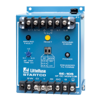
The green POWER LED indicates that the internal
power supply is on. The red GROUND-FAULT LED
indicates a ground-fault trip and the green GROUND-
CHECK LED indicates a valid ground-check loop. When
a ground-fault trip occurs, the SE-105 remains latched
until the reset switch is pressed or the supply voltage is
cycled. The ground-check circuit is non-latching and
does not require a reset. Terminals are provided for
remote indication and reset as shown in Fig. 1.
For the latching ground-check option, the GROUND-
CHECK LED is red and it indicates a latched ground-
check trip.
2.3 F
USING
The output contact is protected by fuse F1 (4.0 A, time
delay). The ground-check circuit is protected by fuse F2
(0.5 A, time delay).
3. INSTALLATION
3.1 SE-105
SE-105 outline and mounting details are shown in
Fig. 2. Typical connections are shown in Fig. 1. Connect
supply voltage to L1 and L2. For a 120-Vac supply,
connect supply neutral to L2. For a direct-current supply,
connect supply negative to L2. Connect chassis-bonding
terminal
to ground.
Connect contact terminals A and B as required.
Face-plate LED's are driven in series with remote-
indication LED's. When a remote kit is not used,
terminals CI, +, and GI must be connected for the face-
plate LED’s to operate. These jumpers are installed at the
factory.
Connect terminal GC to the outgoing ground-check
conductor and connect terminal G to ground. To meet
electrical code requirements, do not jumper chassis-
bonding terminal
to terminal G.
Install the upper terminal-block cover to prevent
inadvertent contact with line terminals.