2
Rear View
Product Overview
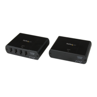
The Local Extender
The Local Extender connects to the computer using a standard USB 2.0 cable. Power
for this unit is provided by the host computer.
Front View
Item Type Description
1
Power LED
(Blue)
LED turns on when power is supplied, o when no power is supplied by the
host computer.
2
Link LED
(Green)
Indicates a valid USB link is established between the Local and Remote
units. The LED turns on when a link between Local and Remote Extender is
established and turns o when there is no link. Fast blinking indicates the
unit is in “Pairing Mode” while slow blinking indicates the unit is attempting
to establish a link.
3
Host LED
(Green)
Indicates that the extender is properly connected to the host computer. The
LED blinks when the extender is in a suspended state.
4
Activity LED
(Amber)
Indicates data transmission is occurring between the Local and Remote
units. The LED blinks intermittently with or without a USB device connected.
When the Local and Remote Extender are in suspend mode the LED is o.
5 Pair Used to establish a paired connection between Local and Remote Extenders.
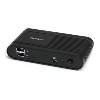
6 USB Host Port
Used to connect the Local Extender to the host computer. Accepts a USB
Type B connector into the Local Extender.
7
Link Port
(RJ45)
Accepts a RJ45 connector for Cat 5e (or better) cabling to connect the Local
Extender to the Remote Extender.
8 Cong Reserved.