7 / 8
14
Bezeichnung
Designation
Symbol
Kodier-Nr�
Coding-No�
Farbe
Colour
(UL)
Phase 1 L1 C1 Braun / Brown
Phase 2 L2 C2 Orange oder violett / Orange or violet
Phase 3 L3 C3 Gold / Yellow
Neutral N C4 Weiss / White
Erde / Ground PE C5 Grün / Green
Reserve - C6
Gleichstrom / Direct current -/+ CM/CP
CM: schwarz / CP: rot
CM: black / CP: red
Kodierung Coding
Es gibt max� 7 mechanische Kodiermöglichkeiten, gekennzeich-
net mit C1 bis C6 und CM/CP�
Folgende Kodierzuordnung wird zur Sicherstellung der Auswech-
selbarkeit empfohlen:
There is a maximum of 7 mechanically coding possibilities, desig-
nated from C1 to C6 and CM/CP�
The following coding is recommended to safeguard the inter-
changeability:
Hinweis:
Es sind nur Stecker mit Buchsen steckbar, die die gleiche
Kodier-Nr� aufweisen�
Note:
Plugs can only be inserted into sockets with the same code
no�
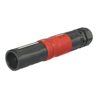
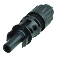
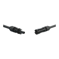
Steckvorgang Plugging procedure
(ill. 14)
Der Verriegelungsstift auf der Buchsenseite muss auf Position
“oen” stehen (ill� 16, Seite 8)�
Zum Stecken müssen sich die Markierungen von Stecker und
Buchse gegenüberstehen� Steckverbindung bis zum Anschlag
zusammenstecken, dann die Buchse um 45° nach rechts drehen,
bis die Verriegelung einrastet�
Wenn gewünscht, Verriegelungsstift auf „geschlossen“ drehen (ill�
17, Seite 8)�
(ill. 14)
The locking pin on the female connector must be in “open” posi-
tion (ill� 16, page 8)�
The markings on the plug and socket have to be lined up� Push
the plug into the socket and press against the plug’s spring resis-
tance until it stops� Turn the socket through 45° to the right until
the bayonet lock engages�
If desired, turn the locking pin to “closed“ position
(ill� 17, page 8)�
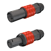
Prüfvorgang Test procedure
Durch Drehbewegung prüfen ob die Verriegelung im Eingri ist�
Durch Zug prüfen, ob die Verbindung in dieser Position mecha-
nisch nicht mehr getrennt werden kann�
By twisting the connectors test that the locking mechanism is
engaged�
By attempting to simply pull the connectors apart, test that the
connection in this position can no longer be mechanically separat-
ed�
Hinweis:
Die korrekte Verriegelung ist erst nach dem Einrasten der
Schiebehülse sichergestellt�
Note:
Correct interlocking is achieved only after engagement of the
sleeve��
45°
Markierung / Marking
Markierung / Marking

 Loading...