5 / 12
Leitfaden zur Konfiguration der Steckverbinder Guideline for configuring the connectors
Hinweis:
Liegt der verwendete Leitungsdurchmesser zwischen zwei
Grenzen, so verwenden Sie bitte den kleineren Dichteinsatz�
Note:
Please use the smaller sealing size if the cable diameter used
is between two limits�
Auswahl von nach TÜV-Rheinland geprüften
Steckverbinderkonfigurationen
An den Steckverbindern angeschlossene Leitungen müssen für
die Verwendung in photovoltaischen Systemen geeignet sein und
den Anforderungen von IEC 62930 entsprechen�
Choose connector configuration verified by TÜV-
Rheinland
Cables connected to the connector shall be suitable for use in
photovoltaic systems and shall comply with the requirements of
IEC 62930�
Hinweis:
Bezüglich der Auswahl der PV Leitungen müssen folgende
Punkte berücksichtigt werden:
- Das Mantelmaterial der PV-Leitung muss Isolierstoklasse 1
nach IEC 60664-1 erfüllen�
Note:
Following points must be considered when selecting the PV
cable:
- The sheath material of the PV cable has to meet insulation
class 1 according to IEC 60664-1�
Auswahl der Steckverbinderkonfiguration bei Ver-
wendung von UL-zertifizierten Leitungen
Bei Verwendung von ausschließlich UL-zertifizierten Leitungen
passende Konfiguration anhand Tab� 2 auswählen:
Selection of connector configuration when using
cables certified at UL
Select the suitable configuration in Tab� 2 by using UL certified
cables only:
Achtung
Crimpen Sie diese Steckverbinder nicht an Leitungen mit
einfach ummantelter Isolierung aus vernetztem Polyethylen
(XLPE Leitung)� Der Einsatz dieses Leitungstyps in Verbin-
dung mit MC4-Evo 2 Steckverbindern erfüllt nicht die UL
6703 Anforderungen bzgl� der Zugentlastung�
Attention
Do not assemble to single jacket cross-linked polyethylene
cable (XLPE cable)� The use of this cable type with MC4-Evo 2
connectors does not fulfill the strain relief requirements of UL
6703�
Leitungsquerschnitt
Conductor cross section
b: Kontrollmaß
b: control measure
Typ
Type
mm
2
AWG mm
1.5 – 2.5 14 ~ 4 PV-K...T4-EVO 2/2,5I-UR PV-K...T4-EVO 2/2,5X-UR PV-K...T4-EVO 2/2,5II-UR
4 – 6 12/10 ~ 5.8 PV-K...T4-EVO 2/6I-UR PV-K...T4-EVO 2/6X-UR PV-K...T4-EVO 2/6II-UR
10 8 ~ 6.5 PV-K...T4-EVO 2/10X-UR PV-K...T4-EVO 2/10II-UR
A: Ø-Bereich der Leitung (mm)
A: Ø-range of the cable (mm)
4.7 – 6.4 5.9 – 7.3 6.4 – 8.4
Verwendbare Dichteinsätze/Usable seals
DI
Rotbraun/maroon
DX
Gelb/yellow
DII
Grau/grey
Tab. 1
b: Kontrollmaß
b: control
measure
Leitungsquerschnitt
Conductor cross section
A: Ø-Bereich der Leitung (mm)
A: Ø-range of the cable (mm)
Kabeltyp
Cable type
TYLZ (USE-2) bis/up to DC 600 V
ZKLA (PV-wire) bis/up to DC 1000 V
4.93 – 6.5 6.5 – 8.5
ZKLA (PV-wire) bis/up to DC 2000 V 5.58 – 6.5 5.76 – 7.45 6.5 – 8.5
mm AWG (stranding) Typ / Type
~ 4 14
(19 – 49)
PV-K...T4-EVO 2/2,5I PV-K...T4-EVO 2/2,5X PV-K...T4-EVO 2/2,5II
~ 5.8 12
(19 – 65)
10
(19 – 105)
PV-K...T4-EVO 2/6I PV-K...T4-EVO 2/6X PV-K...T4-EVO 2/6II
~ 6.5 8
(19 – 168)
PV-K...T4-EVO 2/10X PV-K...T4-EVO 2/10II
Verwendbare Dichteinsätze/Usable seals
DI
Rotbraun/maroon
DX
Gelb/yellow
DII
Grau/grey
Tab. 2
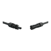
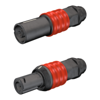
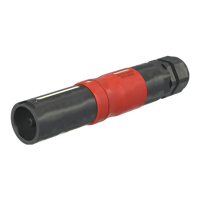
ill. 7
ill. 7

 Loading...