7 / 12
9
11
10
12
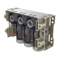
Crimpen Crimping
(ill. 9)
• Klemmbügel (K) önen und festhalten�
• Kontakt in den passenden Quer-
schnittsbereich einlegen�
• Crimplaschen (C) nach oben drehen�
• Klemmbügel (K) loslassen�
• Der Kontakt ist fixiert�
(ill. 9)
• Open clamp (K) and hold tight�
• Insert the contact in the appropriate
cross-section range�
• Turn the crimping flaps (C) upwards�
• Release clamp (K)�
• The contact is locked�
Hinweis:
Darauf achten, dass der Kontakt
in der Aufnahme liegt und durch den
Klemmbügel gehalten wird�
Note:
Make sure that the contact is
placed in the housing and is held by
the clamping bracket�
(ill. 10)
Zange leicht zusammendrücken, bis
die Crimplaschen sicher innerhalb des
Crimpeinsatzes liegen�
(ill. 10)
Press the pliers gently together until
the crimping flaps are properly located
within the the crimping die�
(ill. 11)
Abisolierte Leitung einführen, bis die
Litzen des Kabels am Klemmbügel an-
schlagen� Crimpzange ganz schließen�
(ill. 11)
Insert the stripped cable end until the
cable strands come up against the
locator� Completely close the crimping
pliers�
(ill. 12)
Crimpung optisch kontrollieren bezü-
glich der Kriterien, die in IEC 60352-2
beschrieben sind�
(ill. 12)
Visually check the crimp according to
the criteria written in IEC 60352-2�
Sicherstellen, dass:
• alle Litzen in der Crimphülse einge-
schlossen sind
• die Crimphülse nicht deformiert ist
und kein Teil der Crimplaschen fehlt
• die Crimpung symmetrisch ist
• auf der Kontaktseite der Crimpung ein
„Bündel“ Litzen sichtbar ist�
Confirm that:
• all of the strands have been captured
in the crimp sleeve
• the crimp sleeve is not deformed or
missing any portion of the crimp flaps
• that the crimp is symmetrical
• a “brush” of conductor strands are
visible on the contact side of crimp�

 Loading...