- 33 -
STC8H Series Manual
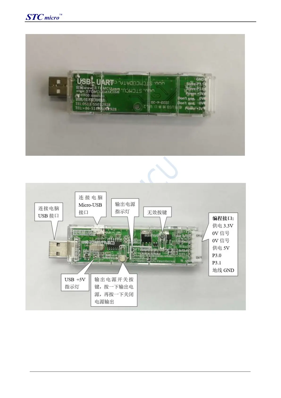
4.2 STC general USB to serial tool layout diagram
Here, the "power switch" needs to be explained:
The function of this button is the same as the self-locking switch. When the switch button is pressed for the first time,
the switch is turned on and held, that is, self-locking. When the switch button is pressed for the second time, the
switch turns off the power. In view of the characteristics of self-locking switches that are easily damaged during use,
we have designed a set of circuits that use light touch switches to replace self-locking switches to increase the service
life of the tools.
For STC microcontrollers, if you want to perform ISP download, you must receive the serial port command at power-
on reset to start executing the ISP program, so the correct steps to download the program to the MCU using the STC
universal USB to serial tool are:
STC Tool Instruction Manual