The following optional devices support the transfer protocol used by the inverter:
• StecaGrid Vision remote display: display of the data from inverters connected to the RS485 bus
• PC or notebook (with suitable software, for technical professionals only):
– Load firmware updates
– Read inverter information using Steca service software
– An optional RS485/USB adapter for connecting to the inverter is also available. The adapter is
available from Steca.
• External data loggers (optional), recommended by Steca for professional system monitoring:
– StecaGrid Monitor
– WEB‘log (Meteocontrol)
– Solar-Log (Solare Datensysteme)
Note
The correct settings must be made in external data loggers, according to the manufacturer's instruc-
tions, before connecting them to the bus.
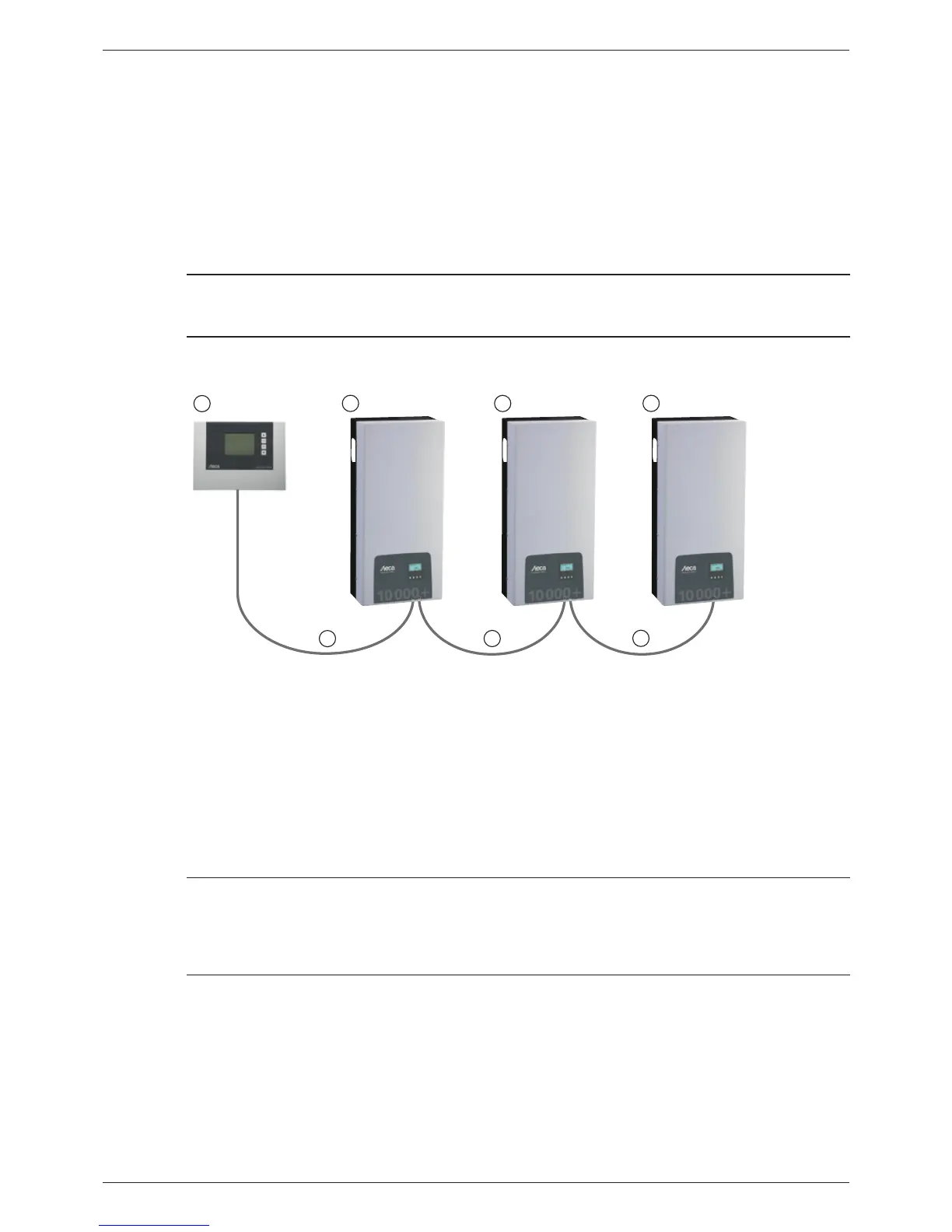
The wiring diagram of the RS485 bus is shown below.
1
2
3
4
6
5
5
RS485
RS485 RS485
Fig. 6: Wiring diagram, using the StecaGrid Vision remote display as an illustrative example
Optional: StecaGrid Vision or external data logger (here: StecaGrid Vision)
First inverter
Inverter
Last inverter, terminated
Data cable (supplied with the device)
Data cable (supplied with the device) or alternative data cable
7.7.4 Alternative data connection cable
Notice
Material damage caused by electrical voltage!
• The alternative data connection cable may only be manufactured by professional personnel.
• To connect it to the RJ45 socket of the first inverter, a HARTING PushPull 10G No. 09 45 145 1560
RJ45 plug must be used to ensure that the inverter meets the specified degree of protection.
The alternative data connection cable is a Cat-5 cable for long data connections. The following ap-
plies to the alternative data connection cable:
• The total length of the RS485 bus must not exceed 1,000 m (Master/first inverter to last inverter).
• Use a 1:1 pin assignment if the alternative data connection cable is connected to the RJ45 sock-
ets of the inverters and the StecaGrid Vision.
• Use the pin assignment according to Tab. 8, p. 56 if the alternative data connection cable
is connected to the RJ45 socket of the first inverter and to the COMBICON connector of the
StecaGrid Vision or to the connector of an external data logger.
55
744.378 | 12.13
EN