18
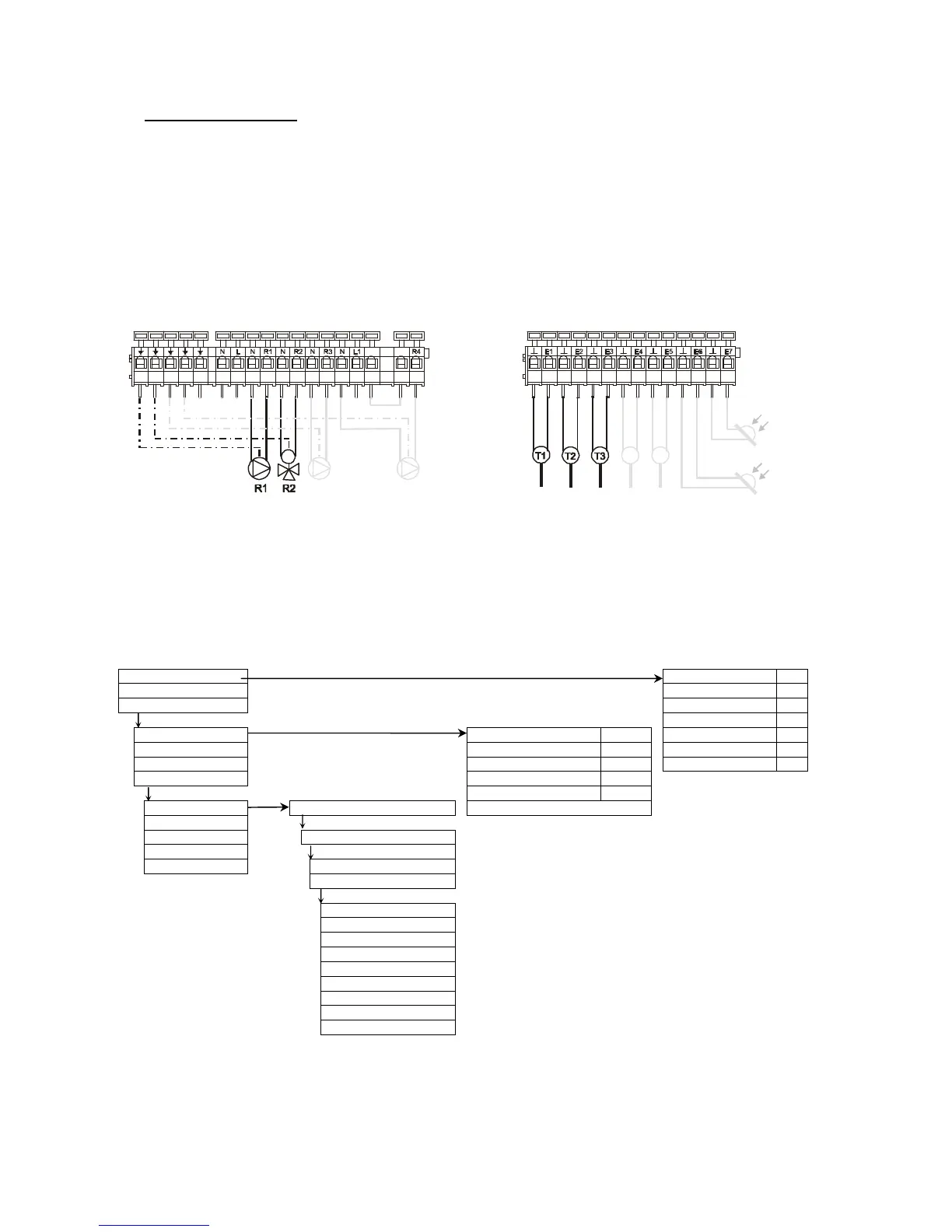
• "Basic V - R" diagram: In some cases the solar circuit pump needs to be controlled according to
the solar radiation. For this purpose the radiation sensors S6 and S7 must be installed in the
corresponding collector levels. For control reasons, T1 must be inserted between the collector’s
collection point and bypass. The temperature sensor T2 is not required. A functional description of
this add-on can be found on page 15.
To prevent erroneous settings, the described switch-on and switch-off values are interlocked,
this means they can be set only at a specific value to one another.
Connecting diagram:
Menu navigation: (here for the scheme 'Basic V' )
OK
Measuring values collector 1: °C
Operating status collector 2: °C
+Settings storage bottom: °C
OK OK
sola