EasyManua.ls Logo

Steca TR 0704 - Page 34

Steca TR 0704
84 pages
Print Icon
To Next Page IconTo Next Page
To Previous Page IconTo Previous Page
Loading...
34
To prevent erroneous settings, the described switch-on and switch-off values are interlocked,
this means they can be set only at a specific value to one another.
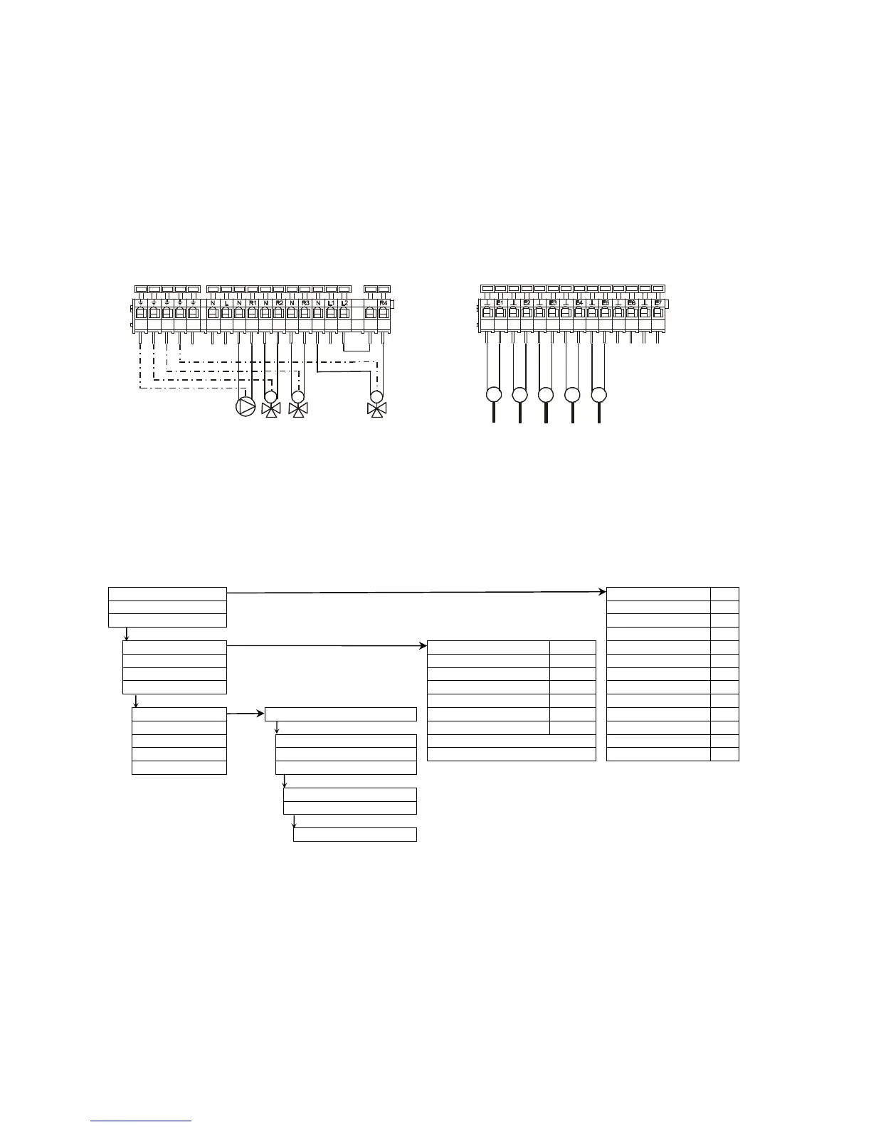
Connecting diagram:
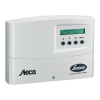
Menu navigation: (here for the scheme 'Basic V' )
OK
Measuring values collector 1: °C
Operating status collector 2: °C
+Settings storage 1 bottom: °C
OK OK
storage 2 bottom: °C
Parameter storage 1 max. 60°C storage 3 bottom: °C
Date / Time storage 2 max. 60°C
sola
r
-
um
Δ:
h
+Clocks storage 3 max. 60°C
sola
r
-
p
um
p
Σ:
h
+Service collector max. 130°C
valve collector Δ:
h
OK OK + Menu (2 sec.)
Diff. temp. solar ON 8K
valve collector Σ:
h
System selection -intern. heat exchanger Diff. temp. solar OFF 4K
valve stora
g
e1 Δ:
h
Functions
OK
switch collect. 10K
valve stora
g
e1 Σ:
h
Links
+1storage tank
storage tank priority...
valve stora
g
e2 Δ:
h
Extras
+2storage tanks
+speed control
valve stora
g
e2 Σ:
h
Manual operation
- 3storage tanks
OK
+1collector
- 2collector
OK
~BasicV
choose with OK (2sec.)
T2 T3 T4
T1
T5
R1
R2 R3
M
R4
MM

Related product manuals