78
Error indication in the regulator’s LCD display:
The error messages at issue can be read in the ´Operating status´ submenu.
Short circuits and disconnections of the individual temperature sensors are then displayed only when
the corresponding sensors are actually really used on account of the selected layout plan and the
activated functions. The regulator automatically detects the following errors and shows these in the
display. If, despite the error display, a malfunction is not rectified but is still acknowledged, there will
be another error display after a few seconds. When several errors occur at the same time the error
with the lowest value (e.g. first T1 then T2 etc.) is displayed.
Note: If a sensor error is detected by the regulator, all of the regulator’s control-related outputs are
switched off for safety reasons until the error is rectified again or disappears by itself. When the
affected outputs can be switched back on therefore depends on the error itself and not on
acknowledgement of the error message. This means unnecessary downtime of the system is reduced
to a minimum.
Meaning of individual readout displays:
Short circuit E1 (Regulator) Short circuit of the temperature sensor line on E1 of the regulator
...
Short circuit E1 (IOBox1) Short circuit of the temperature sensor line on E1 of the IO box 1
...
Short circuit E1 (IOBox2) Short circuit of the temperature sensor line on E1 of the IO box 2
Interrupt. E1 (Regulator) Interruption of the temperature sensor line on E1 of the regulator
...
Interrupt. E1 (IOBox1) Interruption of the temperature sensor line on E1 of the IO box 1
...
Interrupt. E1 (IOBox2) Interruption of the temperature sensor line on E1 of the IO box 2
If there is an error (short circuit or interruption ) on one of the temperature sensor lines or if the input of
a not (or incorrectly) connected IO box is selected, the error message ‘Err°C‘ will be displayed in the
‘Measured data ‘ menu instead of the measured value.
Temperature sensor troubleshooting
The temperature is determined by so-called resistance sensors. These are PT1000 type sensors. The
resistance value also changes depending on the temperature. An ohmmeter can be used to check if
there is a sensor defect. To do this, disconnect the corresponding temperature sensor from the
regulator and then measure the resistance value. The following table contains the typical resistance
values depending on the temperature. Please note that slight deviations are allowed.
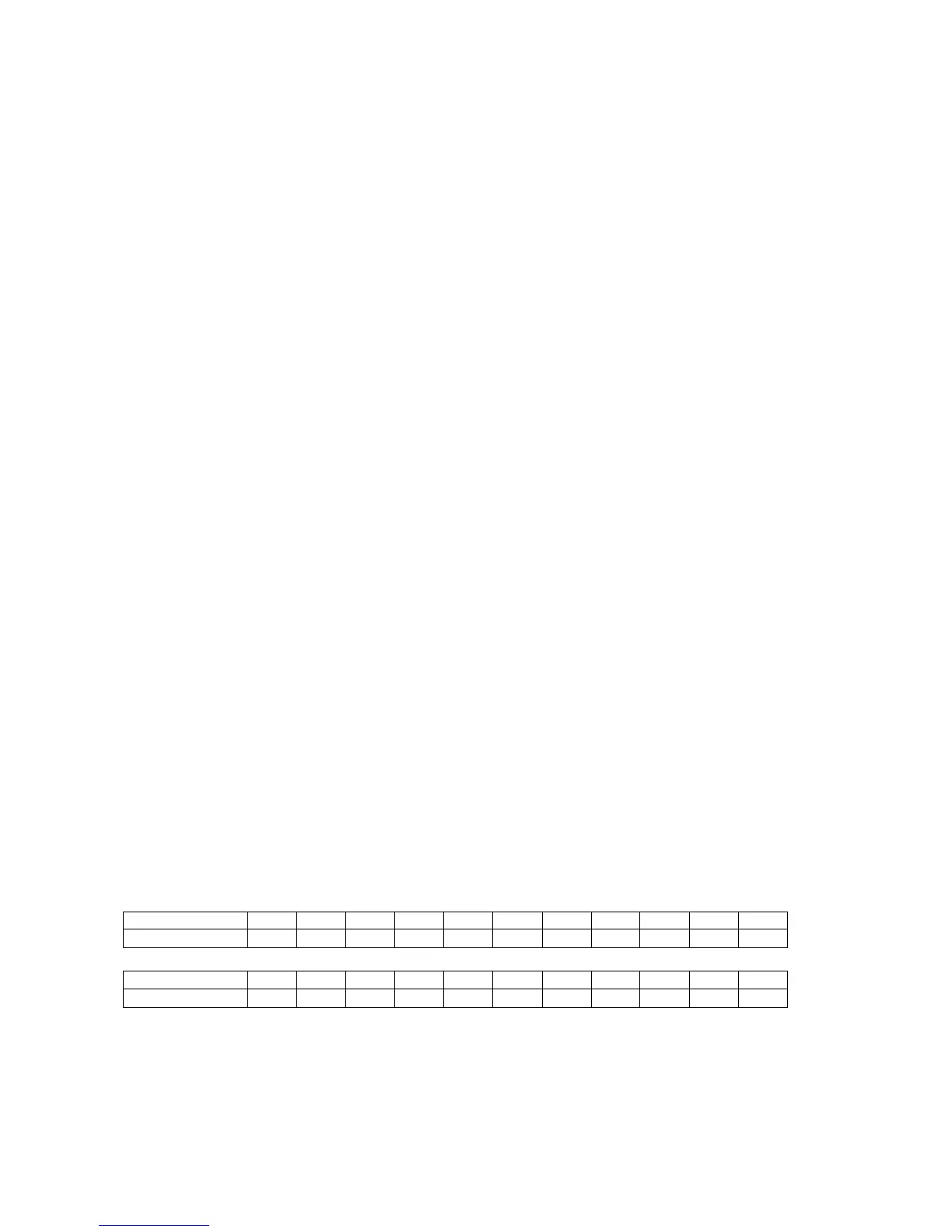
Resistance values of the temperature sensor Pt1000
Temperature [°C] -30 -20 -10 0 10 20 30 40 50 60 70
Resistance [Ω]
882 922 961 1000 1039 1078 1117 1155 1194 1232 1271
Temperature [°C] 80 90 100 110 120 130 140 150 160 170 180
Resistance [Ω]
1309 1347 1385 1423 1461 1498 1536 1573 1611 1648 1685