Step 1 After all brick are loaded, insert the heating elements between the
brick layers, sliding them in until the element ends embed into the
side cutouts of the brick cavity.
3100 Series: The threaded screw tabs on the wire connection
terminals should point forward.
4100 Series: The elements
MUST be installed so their threaded
screw tabs on the wire connection terminals point forward and
down. If they are installed with the screw tabs pointing upward,
element-to-wiring harness connections will be difficult. Be sure
the elements are slid into the brick core properly to ensure correct
clearance between the terminal connections and any surfaces
within the system. Refer to the required clearance information in
Figure 6.
Step 2 Remove the painted front panel of the electrical
compartment by removing the screws along the
edges. Locate the installation hardware package
that is shipped in this compartment.
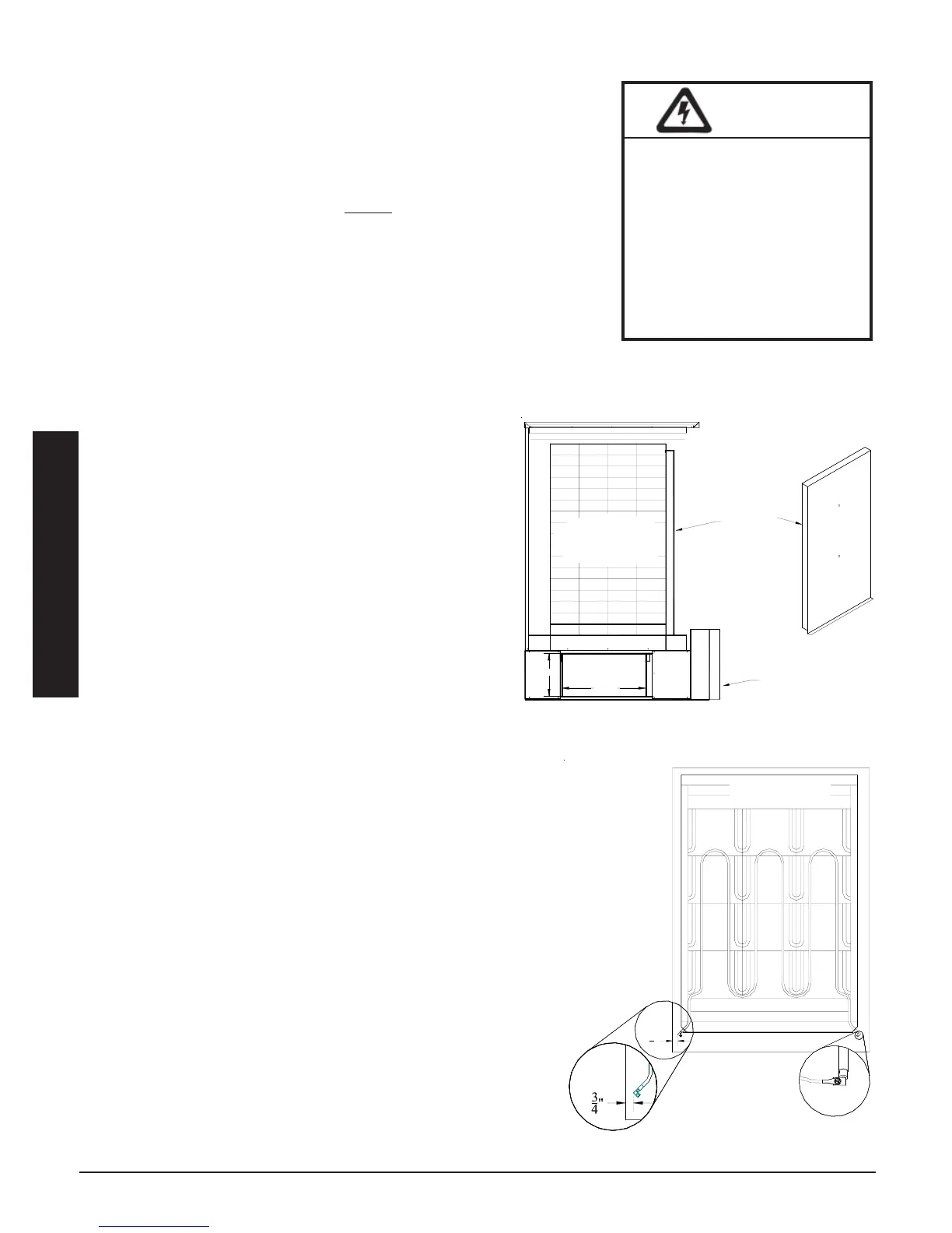
Step 3 Install the front air channel with the air deflectors
(arrow shaped pieces) facing inward and with the
narrow ends of the deflectors pointing up.
3100 Series: Place top portion in first.
4100 Series: Place bottom portion in first (see
Figure 5.)
Step 4 Lower the insulation blankets back into position, one
at a time. Carefully tuck the sides of the insulation
into the edges, corners, and around the exposed
portions of the heating elements to ensure maximum
efficiency.
Step 5 Reinstall the galvanized front panel and secure it to the
Comfort Plus system using the screws that were originally
removed.
3100 Series: Slide the top of this panel inside the upper lip
of the top painted panel. The bottom should rest on the
outside of the cavity and secure to the base with screws.
4100 Series: Slide the bottom of this panel inside the
lower lip of the brick cavity. The top rests on the outside
of the cavity.
Step 6 Carefully route wiring harnesses and connect them to the
heating elements, using screws provided in the hardware
package. Make connections with screw heads up and
threads pointing down. Element screws should be tightened
to 14 inch lbs. Refer to Element Connection (Figure 6) for
proper positioning.
Step 7 The painted front panel can now be installed on 3100
systems. If installing a 4100 system, the brick core tem-
perature sensor(s) must be installed prior to putting the
painted front panel in place.
HEATING ELEMENT AND AIR CHANNEL INSTALLATION
Installation 2.05 Comfort Plus
Installation
Front Air
Channel
Electrical
Panel
BRICK
CORE
SIDE VIEW
20.3"
10.4"
4100 SERIES AIR CHANNEL
PLACEMENT
FIGURE 5
HAZARDOUS VOLTAGE: Risk of
electric shock, injury, or death.
DO NOT remove the electri-
cal panel cover while
system is energized.
Elements MUST be posi-
tioned properly to avoid
short circuiting them against
any surfaces within the
system.
WARNING
3
4
"
Required Clearance Between
Element Termination and Metal
Panels is 1/2" (3/4" Nominal)
Element Connection
ELEMENT INSTALLATION
FIGURE 6
TOP VIEW