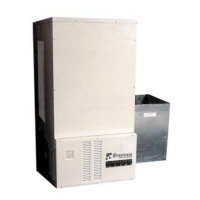
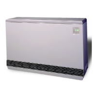
Comfort Plus Installation 2.14
Installation
CONFIGURATION MENU
The Steffes Comfort Plus heating system has a Configuration Menu, which
allows the system to be customized to the power company and consumer’s
needs. This menu can be accessed on start-up and allows configuration
settings to be easily adjusted.
To access the Configuration Menu:
Step 1 Energize the system. Access to the Configuration Menu is allowed
for the first two (2) minutes of operation. If the system has been
energized for more than two (2) minutes, the 15 amp circuit breaker
must be powered off and back on to gain access to this menu.
Step 2 Press and release the M button until faceplate displays “CONF”.
Step 3 Press the up arrow once and the faceplate will display “C000”. The faceplate will flash between
“C000” and the corresponding configuration value.
Step 4 If necessary, edit the configuration value by pressing and holding the M button while using the up or
the down arrow button to change the value.
Step 5 Once the value is correct, release the buttons and press the up arrow button to go to the next configura-
tion (C001,C002, etc.).
Step 6 Repeat steps 4 through 5 until all configuration settings have been adjusted to the desired values.
Step 7 Once configured, use the down arrow to leave the Configuration Menu.
In most applications only a few, if any, configuration changes will be necessary. Following is a description of
the configuration settings and their function:
C000 Off-Peak Method of Charge Control - Sets the method of brick core charging to be used during off-
peak (charge) periods. System is configured for automatic charge control which is a value of five (5).
To utilize manual charge control, change this value to six (6).
C001 Start Brick Core Charge Set Point - If utilizing automatic charge control as set in C000, this value
indicates the outdoor temperature at which the system will start charging.
C002 Full Brick Core Charge Set Point - If utilizing automatic charge control as set in C000, this value
indicates the outdoor temperature at which the system will target a full core charge.
C003 Power Line Carrier (PLC) Channel Selection - If using PLC communication, this setting must match
the channel setting in the Steffes PLC transmitting device. A value of zero indicates power line carrier
communication is disabled.
C004 Optional Controls Configuration
Value Configuration Description
8 No Outdoor Sensor/No Time Clock Module
9 Outdoor Sensor/No Time Clock Module
12 No Outdoor Sensor/Time Clock Module
13 Outdoor Sensor/Time Clock Module
C005 Control Switch Configuration - If utilizing power line carrier control, the Steffes Time Clock Module,
or line voltage control this value should be zero. For all other applications, this value should be one (1).
Configuration Menu continued on next page...
If access to Configura-
tion Menu times out, the
15 amp circuit breaker
must be powered off and
back on to re-enter the
menu.
IMPORTANT