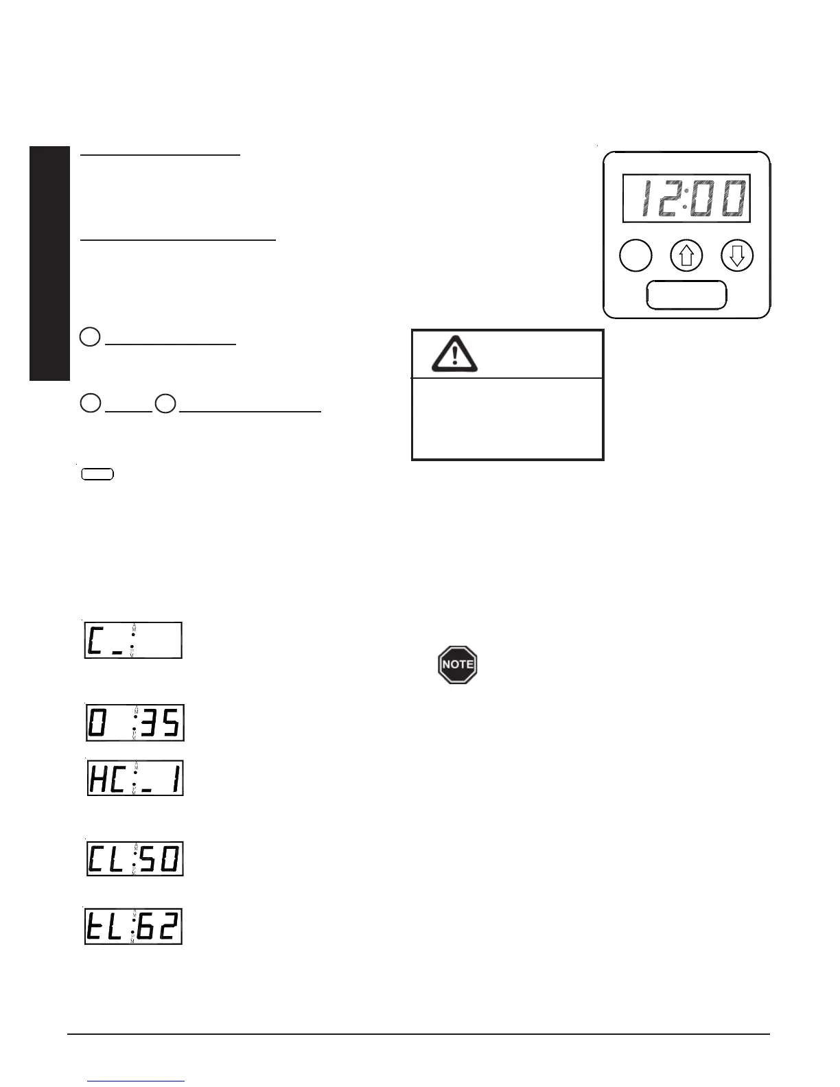
CONTROL PANEL
Operation of the Comfort Plus system is automatic. All operational function settings are stored in a microproces-
sor in factory preset locations. If necessary, the user or installer can adjust these locations settings through the
control panel (Figure 1).
Four-Digit LED Display
The four digit LED displays specific operating information. During an editing process,
the function locations and the values set in these locations are displayed for viewing
and adjusting purposes.
AM and PM Indicator Lights
The AM and PM indicator lights are only utilized if the Steffes Time Clock Module is
being installed. With this module installed, the system displays time on AM/PM
intervals and the corresponding light flashes. The system can be configured to display
military time, in which case, both the AM and PM lights illuminate.
Mode (Edit) Button
Activates the editing menu for changing the operat-
ing information of the system.
Up and Down Arrow Buttons
Used to scroll up or down when viewing or changing
operating functions.
Interface Port
FOR SERVICE USE ONLY! Allows technician external access for updating software and troubleshooting.
OPERATING STATUS
The Comfort Plus is set to display various operating information as described below. Press and release the up
arrow to view this data.
Operating Mode - Indicates the current operating mode of the Comfort Plus system.
C = Off-Peak (Charge) Time
P = On-Peak (Control) Time
A = Anticipated Peak Time
Outdoor Temperature -“O”, followed by a number, indicates current outdoor temperature.
Heat Call Status - Indicates the current heat call status being received from the room thermostat.
HC_0 = No Heat Call HC_1 = Stage 1 Heat Call
HC_2 = Stage 2 Heat Call HC_3 = Emergency Heat
COOL = Cooling/Air Conditioning Call
Brick Core Charge Level - “CL” (charge level) followed by a number, indicates the current
percentage of heat stored in the brick core. “CL:_” represents zero percent and “CL: F” repre-
sents a full core charge level.
Targeted Brick Core Charge Level - “tL” (target level) followed by a number, indicates the
current percentage of brick core charge being targeted by the Comfort Plus. A display of “tL:_”
indicates a target level of zero percent and “tL: F” indicates a full core charge target level.
Operation 1.02 Comfort Plus
M
×
Ø
Operation
A bar illuminates on the lower portion of
the display's second digit whenever the
heating elements are energized.
CAUTION
Editing operating
information may alter
the performance and
operation of the system.
MM
M
PP
AA
MM
STEFFES CORPORATION
CONTROL PANEL
FIGURE 1