Comfort Plus Installation 2.08
Installation
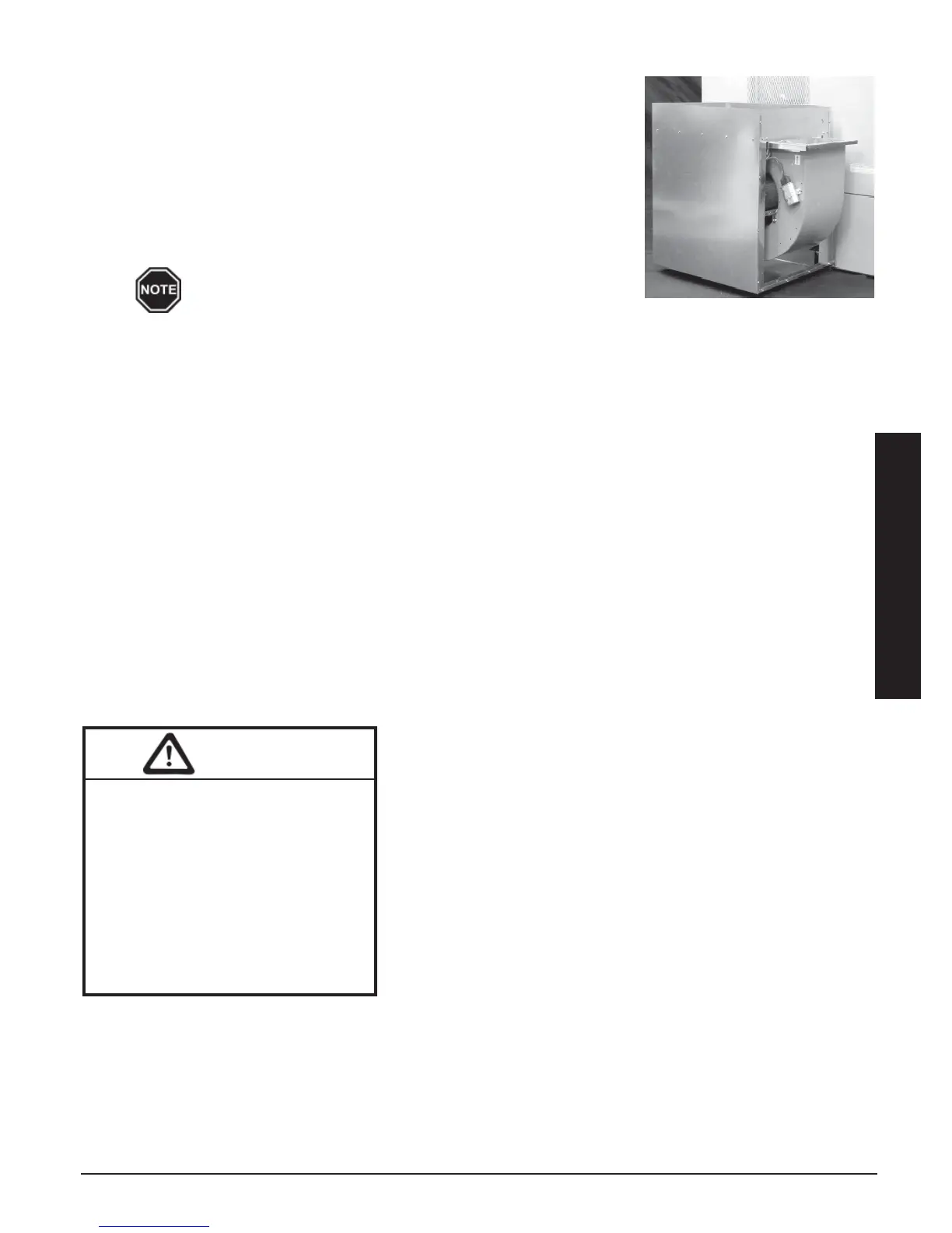
Step 6 Verify that the blower is installed in the plenum with the motor facing
away from the system (Figure 8).
Step 7 Attach the supply air blower plenum to the Comfort Plus by drilling two
1/8” holes per edge and using the self tapping screws supplied in the
hardware package.
Step 8 Connect both the return air and supply air ducting systems in the
structure to the Comfort Plus system. Be sure the air holes just above
the air outlet on the right side are contained in the duct system. (See
Figure 7 for reference to the location of these holes.)
If the Comfort Plus system is installed in a small en-
closed area (less than 400 square feet), a minimum of a
24"x 24" opening must be installed into the area where the system is located. In
addition, a 6" x 6" non-closing type register must be cut into the return air duct. Refer
to the Placement and Clearance Requirements section (Pages 2.02-2.03) for more
information.
AIR CONDITIONER/HEAT PUMP INTERFACE
The Comfort Plus system can accommodate most heat pump or air conditioner indoor coils up to a 4-ton capacity
provided the heat pump or air conditioner is sized in compliance to supply air delivery rates of the Comfort Plus.
Equipment modifications are required to fit larger coils. Refer to the System Air Delivery Matrix (Page 2.07) for
information on air delivery rates of the Comfort Plus supply air blower with regard to the blower's speed. This
information should be used to ensure that adequate air flow is provided for the heat pump or air conditioner being
installed.
The maximum coil size the factory supplied return air plenum can accommodate through the front access is
20”(W) x 21 3/16”(D) x 22”(H). The inner dimensions of the coil area are 21 3/16” (W) x 21 3/16” (D) x 24 1/
4” (H). If installing a coil larger than the access dimensions, the coil MUST be placed in the plenum during
assembly. This return air plenum is a standard piece shipped with the 3100 series systems. In the 4100 series, it
is an optional piece that can be ordered from the factory (Order Item #1041570).
When interfacing the Comfort Plus system with a heat pump, the
indoor coil MUST be placed on the return side of the Comfort Plus
system in a position that will provide even air flow through the coil.
If using a factory supplied return air plenum, the plenum is config-
ured to be the housing for the indoor coil. Remove the screws to
the plenum’s access cover and slide the coil into place inside the
plenum. If not using a Steffes supplied return air plenum, the
installer will need to make provisions in the plenum to accommo-
date the coil and air filter.
When interfacing a Comfort Plus system with an air conditioner,
the indoor coil can be placed on either the supply air or the return
air side of the system.
The condensate drain trap, in a heat pump or air conditioner
installation, should be designed for the vacuum in which the system
is operating. Typically, taller traps are better suited for these types of applications.
Refer to the Room Thermostat Connections Diagrams (Figures 12 and 13) for more information on interfacing the
Comfort Plus with a heat pump or air conditioner.
WARNING
Risk of fire. Any one ducting system
MUST NOT contain more than one
air handling (blower) system. If the
application requires multiple Com-
fort Plus systems or it is necessary to
have multiple air handlers share the
same ductwork, you MUST contact
Steffes Corporation. There are
special installation requirements
that MUST be performed in an
application such as this.
FIGURE 8