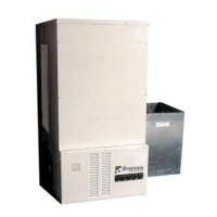
SAFETY PRECAUTIONS
1. DO NOT energize the Comfort Plus while disassembled
or without ceramic heat storage brick in place.
2. DO NOT use or store materials that may produce explo-
sive or flammable gases near the Comfort Plus.
3. DO NOT violate the placement and clearance require-
ments specified in this manual (Pages 2.02-2.03).
4. DO NOT place anything on top of the Comfort Plus.
5. Disconnect power to all circuits before servicing. The
Comfort Plus heating system may be connected to more
than one branch circuit.
6. Installation of and/or service to the Comfort Plus heating
system should be performed by a qualified technician in
compliance with information contained herein and with
national, state, and local codes and requirements.
7. A repeated message of “CORE FAIL” indicates a need
for service by a qualified technician.
BUILT-IN SAFETY DEVICES
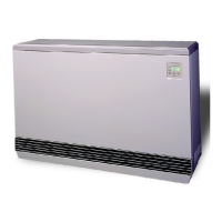
The Comfort Plus heating system incorporates safety devices to ensure normal operating temperatures are main-
tained. The chart below describes these safety devices.
DEVICE NAME FUNCTION
LOCATION
ON SYSTEM
Core Charging High
Limit Switches
(Auto Reset)
These limit switches monitor brick core charging and
interrupt power to the heating elements if the normal
operating temperature is exceeded.
This limit switch monitors the discharge air temperature
and interrupts power to the core blower(s) if the normal
operating temperature is exceeded:
3100 Series = 130
o
F (nominal)
4100 Series = 170
o
F (nominal)
Core Blower
Limit Switch
(Auto Reset)
This limit switch monitors the discharge air temperature
and interrupts power to both the supply air blower and the
core blower(s) if the normal operating temperature is
exceeded:
3100 Series = 160
o
F (nominal) Auto Reset
4100 Series = 190
o
F (nominal) Manual Reset
Supply Air Blower
Limit Switch
Base Temperature
Limit Switch
(Auto Reset)
This limit switch monitors the temperature in the base of the
Comfort Plus and interrupts power to the core blower(s) if
the normal operating temperature is exceeded.
In the base of the
Comfort Plus near the
core blower(s).
In the limit bar panel
on the left side of the
brick storage cavity.
3100: In the discharge
air supply outlet.
4100: On the dis-
charge air
supply blower.
3100: In the discharge
air supply outlet.
4100: On the dis-
charge air
supply blower.
Comfort Plus Safety Information
WARNING
Hazardous Voltage: Risk of elec-
tric shock. Can cause injury or
death. This system may be con-
nected to more than one branch
circuit. Disconnect power to all
circuits before installing or ser-
vicing. Installation of and/or
service to this equipment MUST
be performed by a qualified
technician.
Risk of injury or fire. Violation of
the clearance requirements can
cause improper operation of the
equipment. Maintain the place-
ment and clearance requirements
specified.