RP
O
Y
Terminals for Connection with Heat Pump
Terminals for Connection as a Stand Alone Furnace
W
GRC
Y2
YGRC
Peak Control Connections
SC RSW2 OSY2
RSSCE
W
OSO2
AP
P
COM
NONC
50 VA
TRANSFORMER
M
M
M
P
A
YELLOW
YELLOW/BLUE
ORANGE
ORANGE/BLUE
BLUE/WHITE
BLUE
BLUE/RED
PURPLE
GRAY
GRAY/WHITE
BROWN
BROWN
BLACK
BLUE/WHITE
BLUE/YELLOW
GREEN
ORANGE
YELLOW
WHITE
RED
BLUE/RED
DISCHARGE AIR SENSOR
BLUE
YELLOW
YELLOW
YELLOW
RED
RED
UPPER CORE THERMOCOUPLE
LOWER CORE THERMOCOUPLE
3120/4130/4140
3120/4120/4130/4140
-
+
-
+
(OPTIONAL 75VA)
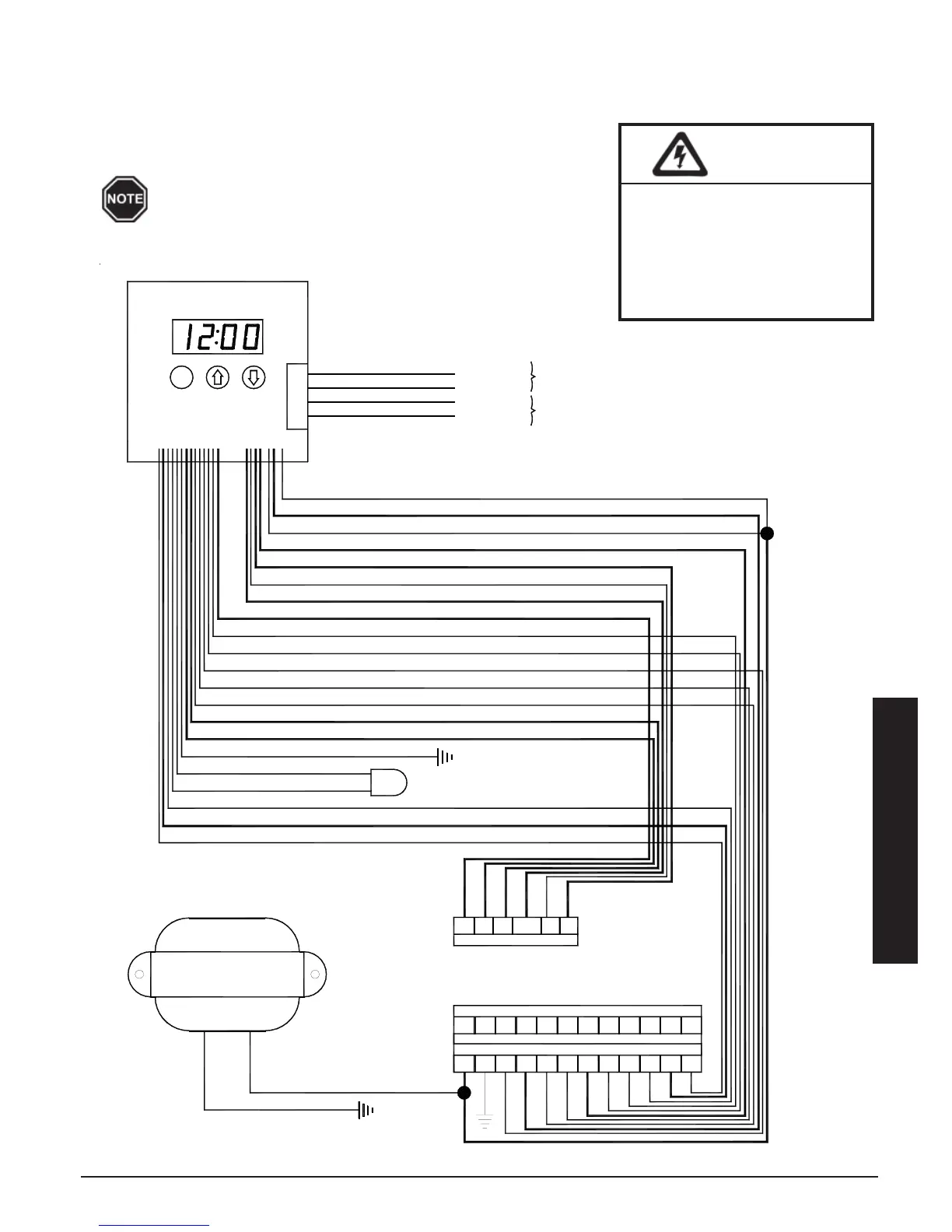
Comfort Plus Appendix A.12
INTERNAL SYSTEM WIRING DIAGRAM - LOW VOLTAGE
The outdoor temperature sensor, room thermostat, and peak control device are connected via low voltage wiring.
System Low Voltage Wiring Diagram
Appendix
The "R" and "C" positions in the low voltage terminal
strip may be used as a source of 24 VAC for powering
external low voltage devices (30 VA maximum).
HAZARDOUS VOLTAGE:
Risk of electric shock, injury,
or death. All low voltage
wiring must be segregated
from line voltage circuits in
the system.
WARNING