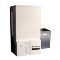
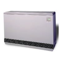
Comfort Plus Installation 2.10
Installation
LOW VOLTAGE ELECTRICAL CONNECTIONS
Steffes ETS heating equipment may
be controlled by the Power Com-
pany via a peak control signal. This
signal can be sent to the equipment
using a Steffes Power Line Carrier
control system, low voltage wiring, a
Steffes Time Clock Module, or line
voltage wiring. In applications
utilizing automatic charge control,
outdoor temperature information is required and can be received via an
outdoor sensor or power line carrier control system.
The Comfort Plus heating system is factory config-
ured for low voltage wire control and is set to
charge when the utility peak control switch closes.
Refer to the Configuration Menu (Pages 2.14-2.15)
for information on configuring the system for the
application.
LOW VOLTAGE (DIRECT WIRED) PEAK CONTROL
If using the low voltage peak control option, the Comfort Plus is direct wired to the power company's peak
control switch. Field connections from the peak control switch are made to the low voltage terminal block
through a low voltage knockout located on the left side of electrical panel.
Step 1 Route a low voltage circuit from the power company’s load control or peak signaling device to the six
(6) position terminal block inside the electrical compartment of the Comfort Plus (see Figure 11).
Step 2 Connect the field wiring to positions "RP" and "P" on the six (6) position low voltage terminal block.
(see Figure 11).
To control other devices, refer to the Auxiliary Load Control on Page 2.13.
POWER LINE CARRIER (PLC) PEAK CONTROL
The Steffes Power Line Carrier (PLC) control system has the ability to communicate with the system through
the existing electrical circuits in the structure. With the power line carrier option, direct wired low voltage
connections from the power company's peak signaling switch connect directly to the transmitting device. The
switch signals peak control times to the transmitter, the transmitter sends the signals to the Comfort Plus system,
which receives this information and responds accordingly.
In addition to providing peak control signals, the transmitter also provides outdoor temperature information for
automatic charge control, room temperature set back, and anticipated peak utility control signals (if applicable).
The PLC system is optional and must be ordered separately. If utilizing a PLC system, an Owner's and
Installer's manual will accompany the transmitting device. Refer to this manual for information on the installa-
tion and operation of the power line carrier control system.
Never install any wiring in
a line voltage compartment
of the Comfort Plus unless
it is rated for line voltage.
IMPORTANT
PEAK CONTROL TERMINAL
CONNECTIONS
FIGURE 11
Dry Contact Peak
Control Switch
NCP
RP
COM
AP
NO
Comfort Plus 6-Position Low Voltage Terminal Block Coding
RP = Peak Control Input Common
P = Peak Control Input
AP = Anticipated Peak (Pre-Peak) Control Input
COM = Peak Control Output Common
NC = Peak Control Output (Normally Closed)
NO = Peak Control Output (Normally Open)