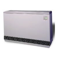
Installation 2.11 Comfort Plus
TIME CLOCK MODULE PEAK CONTROL
The Steffes Time Clock Module is another option for providing a peak control signal to the Comfort Plus. The
optional time clock module mounts inside the line voltage electrical compartment and interfaces with the relay
board via an interface cable. Peak control times MUST be programmed into the system once the module is
installed to enable the time clock feature. Refer to the instructions provided with the time clock module for more
information on the installation and operation of this device.
LINE VOLTAGE PEAK CONTROL
Line voltage control is also an option, but is not the preferred method of control as it is usually more complex
and expensive. If line voltage control is utilized, the controls circuit must be powered with an uninterrupted
circuit. An external switching device, such as a relay panel, is necessary to directly control the heating element
charging circuits. If relying on this method of control, the display on the system must continuously display a
brick core operating mode of “C” (charge) regardless of whether it is an off-peak or on-peak period.
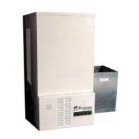
OUTDOOR TEMPERATURE SENSOR
An outdoor temperature sensor, shipped in the electrical
compartment, is required to be installed with the Comfort Plus.
This sensor monitors outdoor temperature and provides this
information to the system. The system responds by automati-
cally storing heat in its brick core according to the outdoor
temperature and the heating requirements.
The outdoor temperature sensor can be installed in one of two
ways: direct wired to the system or wired to the Steffes power line carrier system. The Comfort Plus is factory
configured for automatic charge control with a direct wired outdoor sensor. Refer to the Configuration Menu
(Pages 2.14-2.15) for information on the appropriate settings for the application.
Installing the Outdoor Sensor
Step 1 Select a location and mount the sensor. The outdoor sensor must be placed in a location where it can
accurately sense outdoor temperature and is not affected by direct sunlight or other abnormal tempera-
ture conditions.
Step 2 Route low voltage wire from the outdoor sensor to the electrical compartment through one of the low
voltage wire knockouts.
· If the sensor wiring is routed through an external wall, the opening through which the wire
is routed MUST be sealed. Failure to do so may affect the accuracy of the outdoor tem-
perature sensor.
· The outdoor sensor is supplied with a lead length of 40 ft. If a greater wire length is
needed, it can be extended to a total of 250 ft. No other loads can be controlled or supplied
through this cable. It is for connection of the outdoor sensor ONLY. This low voltage
cable should not enter any line voltage enclosure.
· Unshielded Class II (thermostat) wire can be used as extension wire provided it is segre-
gated from any line voltage cabling.
Step 3 Connect the outdoor sensor wires to the “OS”
and “SC” positions of the twelve (12) position
low voltage terminal block located inside the
electrical compartment of the Comfort Plus (see
Figures 12 and 13).
Installation
If connecting to the Steffes power line
carrier (PLC) system, follow the installa-
tion instructions in the PLC system's
Owner's and Installer's Guide.
IMPORTANT
IMPORTANT
Outdoor sensor wire MUST NEVER be
combined with other control wiring in a
multi-conductor cable.