SYSTEM AIR DELIVERY MATRIX
Installation 2.07 Comfort Plus
Installation
ATTACHING THE DUCTING (3100 SERIES)
Step 1 If using the factory supplied return air plenum (shipped separately), follow the assembly procedure
provided with the plenum.
Step 2 Once assembled, set the plenum on the right side of the system with the air filter and indoor coil access
covers facing forward. Line up the predrilled holes on the system with the holes in the flanges of the
plenum and attach using the screws provided in the plenum's hardware package.
Step 3 Insert the air filter into the filter rack.
Step 4 Connect the supply air duct in the structure directly to the system's air outlet located on the top panel.
Step 5 If necessary, adjust the supply air blower speed by changing the wiring on the blower speed selection
terminals. Refer to the System Air Delivery Matrix for details.
ATTACHING THE DUCTING (4100 SERIES)
Step 1 Remove the supply air blower plenum assembly from
the box.
Step 2 The supply air blower is shipped inside the plenum
assembly in its operating position and is secured to the
plenum by a metal plate to keep the blower from
moving during shipping. The metal plate MUST be
removed before operating the system. Once removed,
it may be discarded.
Step 3 Adjust blower speed, if necessary, by changing the
wiring on the blower speed selection terminals. Refer
to the System Air Delivery Matrix for details. The
front access cover on the supply air plenum will need
to be removed to access these terminals.
Step 4 Locate the plenum support bracket which is shipped in
the plenum box. Attach the bracket to the supply air
side using the blunt tip screws supplied in the plenum
assembly hardware package. Refer to Figure 7 for
proper positioning of the plenum support bracket.
Step 5 Attach the supply blower wiring harness located in the
base of the system to the blower using the connections
located on the ends of the harness. Be sure to place
any excess wiring in the base of the system below the
radiant heat shield (Figure 7).
*Low Speed Maximum Pressure is .25 inches water column.
STATIC PRESSURE (INCHES WATER COLUMN)
Supply Air
Blower Speed 0.10 0.25 0.50 0.75
High (CFM) N/A 1850 1560 1350
Medium High (CFM) 1800 1780 1470 1240
Medium Low (CFM) 1610 1580 1420 N/A
*Low (CFM) 1230 1205 N/A N/A
(External static pressure should not exceed .75 inches water column.)
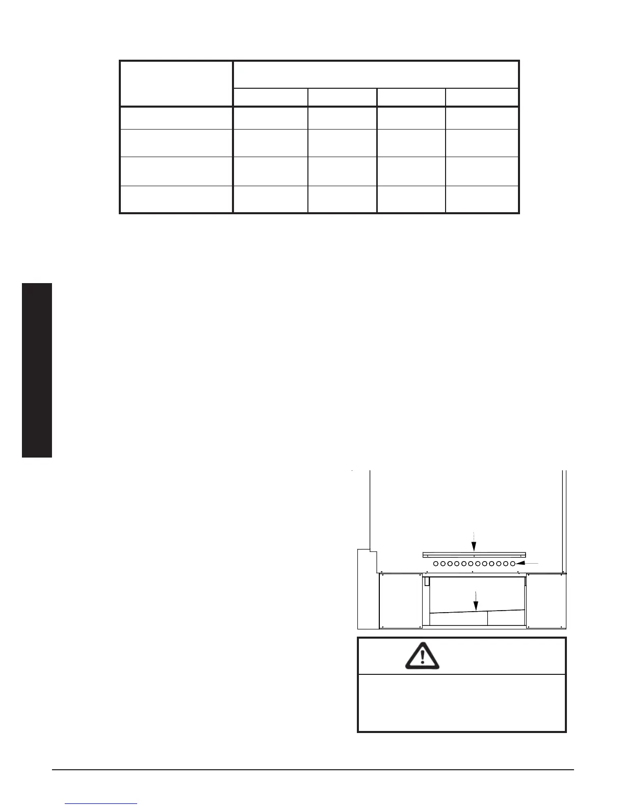
4100 SERIES
SUPPLY AIR PLENUM ATTACHMENT
FIGURE 7
When routing the harness to the supply
air blower, the harness must route to the
side of the air deflector in the bottom of
the supply air blower housing.
CAUTION
Air
Holes
Plenum Support Bracket
Radiant Heat Shield