The Controls and Connectors
10 Getting Started
The Controls and Connectors
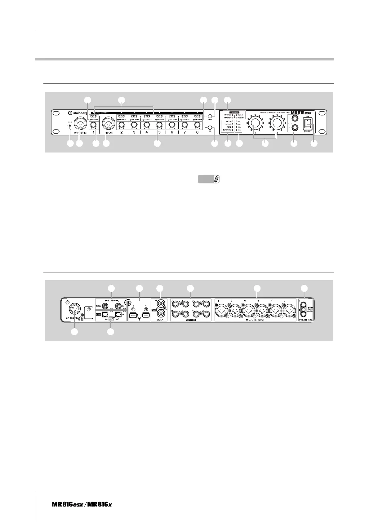
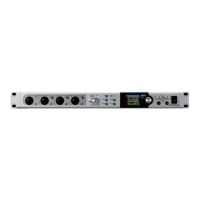
Front Panel
1 [HI-Z] switch
2 MIC/LINE/HI-Z jack 1 (analog input jack 1) and
MIC/LINE jack 2 (analog input jack 2)
3 [QUICK CONNECT] buttons (with LED lamps)
4 [SIG/PEAK] lamps
5 Gain knobs 1 – 8
6 [+48V] button (phantom power button; with LED
lamps)
7 [PAD] button (with LED lamps)
8 [ASSIGN] lamps
NOTE
· The [MORPH] lamp is available only on the MR816 CSX. The
MR816 X is not equipped with the [MORPH] lamp.
9 Word Clock Source lamps
) Sample Rate lamps
! Multi Function encoder knobs 1 and 2 (with LED
lamps)
@ Headphone jacks 1 and 2
# [STANDBY/ON] switch
Rear Panel
1 AC ADAPTOR IN jack
2 S/PDIF IN/OUT jack
3 OPTICAL IN/OUT jack
4 IEEE1394 jack 1 and 2
5 WCLK IN/OUT jack (wordclock in/out jack)
6 OUTPUT jacks 1 – 8 (analog output jacks 1 – 8)
7 MIC/LINE INPUT jacks 3 – 8 (analog input jacks
3 – 8)
8 INSERT I/O jacks 1 and 2
12
43 468
52 5 7 9 ) ! @ #
13
245 6 7 8