14
GB
1. About this document
Please read carefully and keep in a safe
place.
– Under copyright. Reproduction either in whole
or in part only with our consent.
Symbols
!
Hazard warning!
2. General safety precautions
!
Disconnect the power supply
before attempting any work
on the unit.
• During installation, the electric power cable
being connected must not be live.
Therefore, switch o the power first and use
a voltage tester to make sure the wiring is
o-circuit.
• Installing the light involves work on the mains
voltage supply. This work must therefore be
carried out professionally in accordance with
national wiring regulations and electrical op-
erating conditions. (e.g. DE - VDE 0100, AT -
ÖVE / ÖNORM E8001-1, CH- SEV 1000)
• Only use genuine replacement parts.
• Repairs may only be made by specialist
workshops.
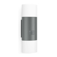
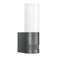
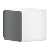
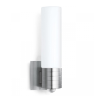
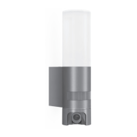
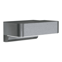
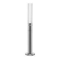
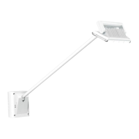
3. L910S, L910, L930S, L930
Proper use
L910S, L930S
– LED uplight / uplight-downlight with infrared
sensor.
Proper use
L910, L930
– LED uplight / uplight-downlight.
L910S, L930S:
The integrated infrared sensor detects the invis-
ible heat radiated from moving objects (people,
animals, etc.).
The heat detected in this way is converted
electronically into a signal that switches the light
ON automatically. Heat is not detected through
obstacles, such as walls or panes of glass, and
will therefore not activate the light.
Twilight-controlled eect lighting on the wall
can be selected as an option.
Important:
The most reliable way of detecting motion is to
install the light with the sensor aimed across
the direction in which a person would walk and
by ensuring that no obstacles (such as trees
and walls, for example) obstruct the line of
sensor vision. Reach is limited when walking
directly towards the light.
Package contents (Fig. 3.1/3.2/3.3/3.4)
– Light
– Wall mount
– Three screws
– Three wall plugs
– Three spacers
– Two retaining screws
Product dimensions L910S, L910 (Fig. 3.5)
Product dimensions L930S, L930 (Fig. 3.6)
Product components (Fig. 3.7/3.8)
A Wall mount
B Connecting terminal
C Light enclosure
D IR sensor (L910S, L930S only)
Detection zone (Fig. 3.9)
(L910S, L930S only)
L910S, L910 luminous intensity distribution
(Fig. 3.10)
L930S, L930 luminous intensity distribution
(Fig. 3.11)