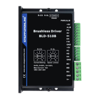
BLD-510B BLDC
B
r
u
s
h
l
e
ss
Driver
4.3 Motor run/stop control (EN)
The motor can be controlled to run and stop by controlling the switch-on and switch-off of the terminal EN in
relation to GND. Currently the driver has 2 versions, V2.0 and V2.4. For V2.0 Version, motor runs when the
terminal is switched on and conversely the motor stops. While for V2.4 version, motors only runs when the
terminal is switched off and conversely the motor stops. When the motor is stopped using the run/stop
terminal control, the motor is stopped naturally. The law of motion is related to the load inertia.
4.4 Motor forward/reverse control (F/R)
The direction of motor operation can be controlled by controlling the connection of terminal F/R to terminal
GND. When F/R and terminal GND are not switched on, the motor runs clockwise (facing the motor shaft),
and vice versa, the motor runs counterclockwise. To avoid damage to the drive, when changing the motor
steering, the motor should be stopped before operating to change the steering. Changing the direction of
operation while the motor is running should be avoided.
4.5 Braking Stop (BK)
The braking stop of the motor can be controlled by the connection of control terminal BK to terminal GND.
When control terminal BK is disconnected from terminal GND, the motor runs, when it is switched on the
motor quickly brakes to a stop, braking stop is faster than natural stop, the specific stopping time is related to
the load inertia of the user's system.
Attention: As the brake stop has a bad impact on both the electrical and the mechanical, a natural stop should
be used if there are no special stopping requirements.
4.6 Motor Speed Signal Output (PG)
The speed pulse output is a 5V pulse output, to obtain the signal a pull-up resistor of 3K ohm ~10K ohm
should be connected to the power supply. The number of output pulses per revolution of the motor is 3 x N, N
being the number of pairs of poles of the motor. For example: 2 pairs of poles, i.e. a four-pole motor, 6 pulses
per revolution. When the motor speed is 500 rpm, the output pulse of the terminal PG is 3000.
4.7 Alarm Output (ALM)
Alarm output of the driver: this terminal is low during an alarm. To obtain a signal, a pull-up resistor of 3K ohm
to 10K ohm should be connected to the power supply. When the alarm is on, this terminal is connected to
GND (low level) and the driver stops itself and is in alarm.
4.8 Driver Failure
If a fault occurs inside the driver such as overvoltage or overcurrent, the driver enters a protection state, the
driver will automatically stop working, the motor stops and the red light on the driver is always on. The driver
can only disarm the alarm if the enable terminal is reset (i.e. EN is disconnected from GND) or if power is cut
off. Please check the motor wiring or remove the load if this fault occurs.
 Loading...