2
13406 SE 32nd St, BELLEVUE WA, 98005 WWW.CONSUMER.STEPPIR.COM TEL: (425)-453-1910
*Projected area is the total perpendicular surface area measured in square feet/square meters, that is exposed to
wind. To calculate wind load you always take the largest projected area whether that is from the perspective per-
pendicular to the boom or perpendicular to the elements. In the case of SteppIR Yagi's, the maximum projected
area will always be the sum of the surface area's perpendicular to the Yagi elements. This calculation is a constant
number and will not change regardless of EIA specification changes. Do not mistake this projected area calculation
as anything more than a datapoint to present to your structural engineer, tower manufacturer or rotator manufac-
turer so that they can determine what is necessary for your application.
When sizing an antenna to a tower, many factors need to be taken into consideration including, but not limited to:
projected area of antenna in square feet or square meters, weight of the antenna and other items on tower, turning
radius, element lengths, antenna height, location exposure category, locations three-second gust wind-speed, lo-
cations maximum radial ice loading.
Improper specification of an antenna or rotator to a tower can result in product failure, injury or death. SteppIR is
not an expert on tower or rotator sizing and for this reason will never offer any recommendation – this specification
process is meant for industry professionals such as a structural engineer, tower manufacturer or rotator manufac-
turer. Please do not attempt to self-specify our products – the information provided by SteppIR is to be utilized by
industry professionals only and we will not accept any liability for improperly specified antenna/tower/rotator appli-
cations.
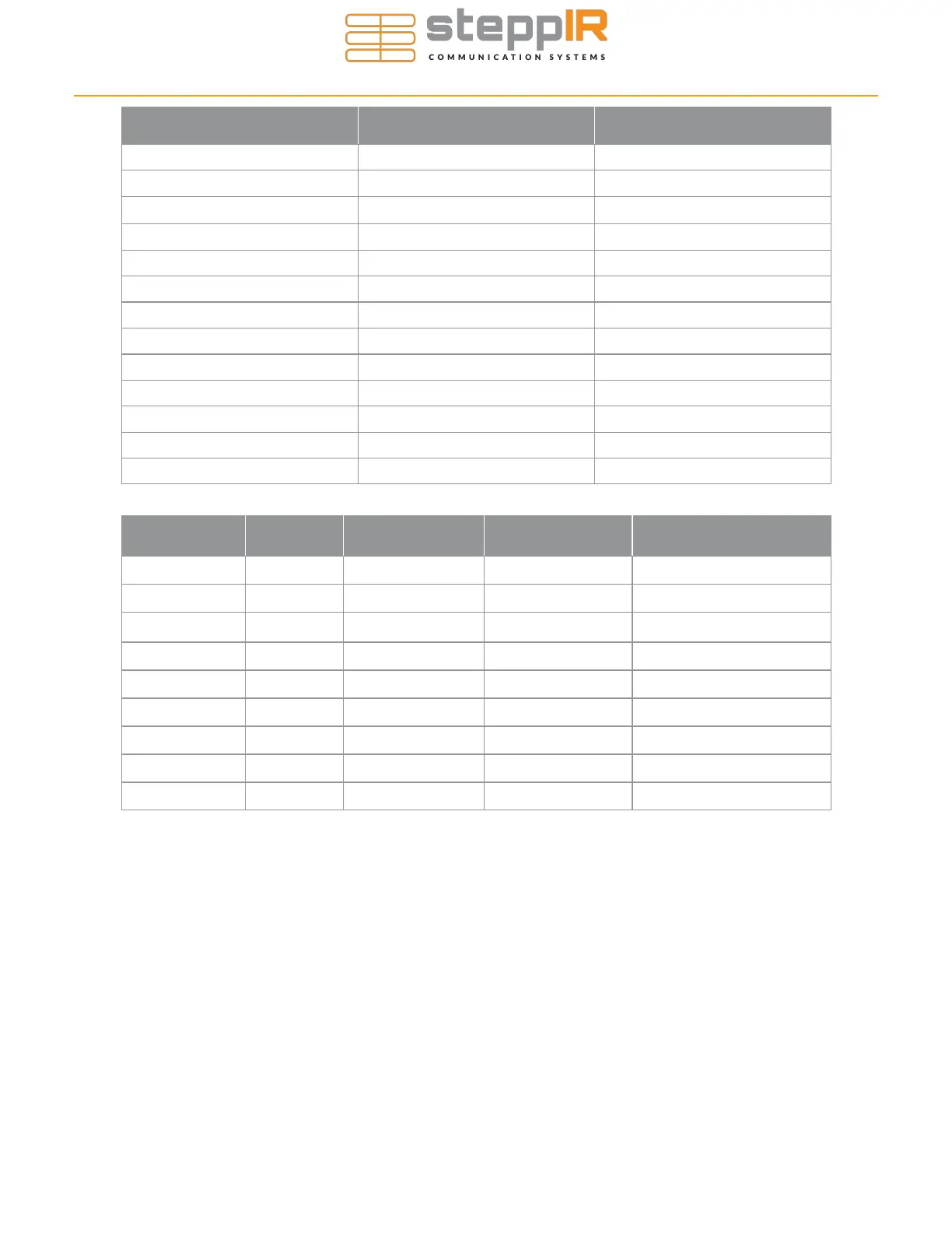
Specification 2 Element Yagi
2 Element Yagi + 40/30 Loop
Boom length 60” (61.5” overall length)
60” (61.5” overall length)
Boom outside diameter 1-3/4”
1-3/4”
Longest element 36 ft
39 ft
Turning radius 18.94 ft
20.4 ft
Weight 30 lb
37 lb
Projected Area* 7.27 sq ft / 0.66 sq m
10 sq ft / 1.01 sq m
Wind rating 100 mph
100 mph
Adjustable elements 2
2
Power rating 3 kW continuous
3 kW continuous
Feed points 1
1
Frequency coverage 13.85 MHz - 54 MHz
6.95 MHz - 54 MHz
Tuning rate 1.3 ft/s
1.3 ft/s
Control cable 12 conductor 22awg shielded
12 conductor 22awg shielded
Frequency
2E Gain
dBi
2E Front to rear
dB
40/30 loop gain
dBi
40/30 loop front to rear
dB
40m N/A
N/A 1.8 N/A
30m N/A
N/A 2.1 N/A
20m 6.6
21 N/A N/A
17m 6.6
16 N/A N/A
15m 6.5
13 N/A N/A
12m 6.4
11 N/A N/A
10m 6.2
9 N/A N/A
6m 5.0
2 N/A N/A
6m w/ passive 8.3
20 N/A N/A
ANTENNA SPECIFICATIONS