22
13406 SE 32nd St, BELLEVUE WA, 98005 WWW.CONSUMER.STEPPIR.COM TEL: (425)-453-1910
Section 3.1: Preparing the Control Cable
(if you have pre-wired cable, skip to page 24)
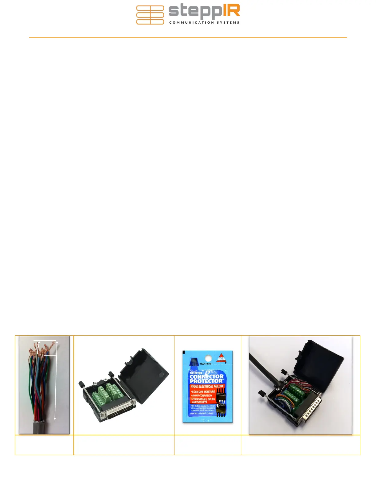
1. Strip the jacket and aluminum shielding off of the control cable as shown in Figure 3.11, approxi-
mately 2.75” from end of control cable, being careful not to damage the individual wires.
2. Strip the plastic insulation off of each of the control cable wires, approximately 0.25” in length should
be bare wire. Tinning of the copper wire ends with solder is NOT recommended by the connector
manufacturer.
Section 3.2: Connecting control cable to the DB25 Field Splice
(if you have pre-wired cable, skip to page 24)
1. Apply the provided dielectric grease to the exposed copper portion of each wire. Figure 3.22 shows
what the connector protector will look like.
The terminals may be closed by default. If so, turn the terminal screw counterclockwise ~10 turns
to open it before inserting the wires.
2. Consult Figure 3.24 on the next page for the correct wiring sequence.
3. Connect each wire to the appropriate terminal and tighten using a flat head screwdriver. Be sure you
are clamping down on bare copper, not the insulation. Verify there is not excessive bare wire
sticking out of the terminal or it may short to other pins/wires.
4. Position the control cable between the cable clamp halves as shown in Figure 3.23. Electrical tape
can be wrapped around the cables to increase the cable thickness if necessary.
5. Tighten the two pan head screws until the cable is snug, but do not over-tighten.
6. Thread the two thumb screws into the connector face as shown in Figure 3.23.
7. Plug the DB25 splice into the back of the controller, ensuring that it is fully seated, and twist the
thumb-screws to secure it. For first time setups it is common for this to be only partially installed, re-
sulting in fault codes on the controller.
Figure 3.11 Figure 3.21 Figure 3.23 Figure 3.22
2.75”
0.25”
WIRING THE CONTROL CABLE TO THE DB25 SPLICE