26
13406 SE 32nd St, BELLEVUE WA, 98005 WWW.CONSUMER.STEPPIR.COM TEL: (425)-453-1910
Section 3.4: Wiring the EHU (skip to page 27 if you have pre-wired cable)
1. Trim approximately 1.5” of the outer jacket of the control cable.
2. Remove the outer foil shield, the support thread, and cut the shield wire off.
3. Attach electrical tape at the end of the trimmed control cable jacket so that there is no chance for a
short.
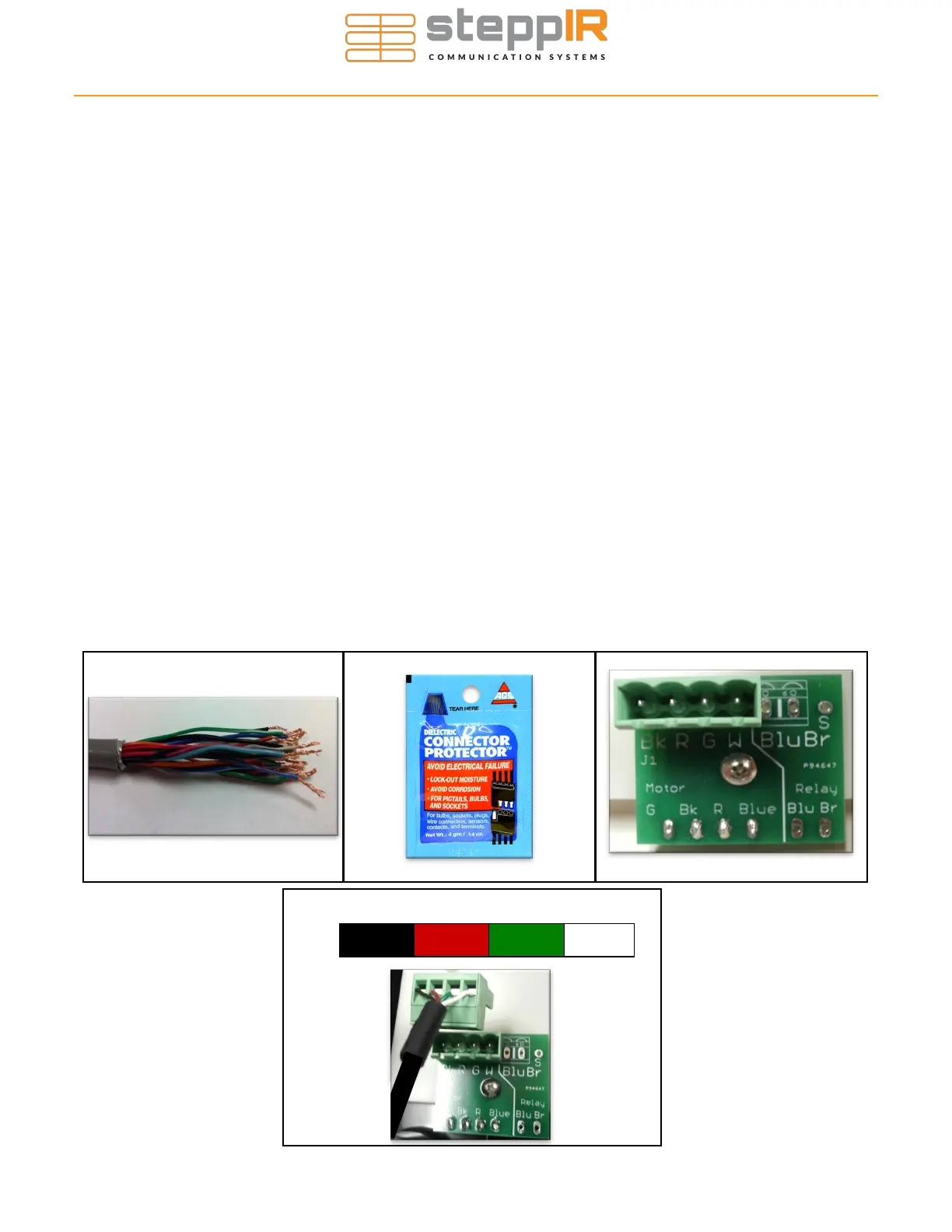
4. Remove 0.25” of the insulation from each of the individual 22 AWG wires, leaving bare copper. Tin-
ning of the copper wire ends with solder is NOT recommended by the connector manufacturer. Fig-
ure 3.41 shows the control cable should look like when you are finished with the trimming.
5. Apply the provided dielectric grease to the exposed copper portion of each wire. Figure 3.42 shows
what the connector protector will look like.
6. The terminal header assembly consists of the terminal header and the terminal plug. The plug is
shipped loosely attached to the header. Remove this plug when wiring and firmly plug back in when
completed (use dielectric grease on this terminal plug to prevent moisture ingress/corrosion).
7. Follow the wire sequence in Figure 3.44. Be careful to ensure that there are no bare wires protruding
out from the terminal clamps, to avoid potential shorts. Also make sure you are clamping down on
bare wire, and not the insulation of the wire. The wiring sequence for the EHU is also imprinted on
the PCB that the terminal header is mounted on (located inside the EHU), as shown in Figure 3.43.
Pay no attention to the second row of imprinted text, these pins are for use in the manufacturing of
the board itself and are of no use to you. Figure 3.43 shows a red line crossing out the text in ques-
tion. The orange circle shows the correct wiring sequence.
BLACK RED GREEN WHITE
4 Pin Header Wiring Sequence
Figure 3.44
WIRING THE EHU
Figure 3.41 Figure 3.42 Figure 3.43
1.5”
0.25