34
13406 SE 32nd St, BELLEVUE WA, 98005 WWW.CONSUMER.STEPPIR.COM TEL: (425)-453-1910
0.25” GAP
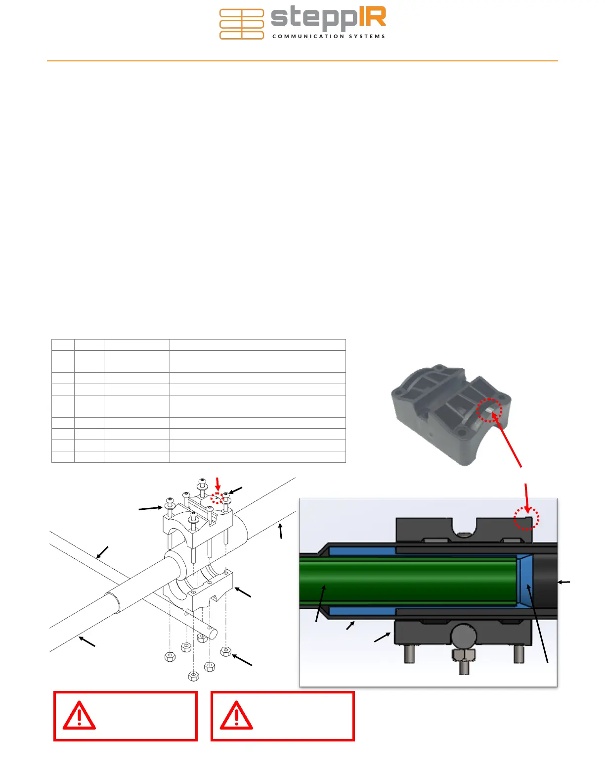
• Refer to Figure 6.26 during the following steps for an overview of the assembly process. You will be
using the hardware from the sweep hardware kit (PN 72-0030-61)
• Each of the sweep coupler halves (E) will have a notch in the mold on one side marked with silver
sharpie. IT IS CRITICAL THAT THESE NOTCHES ARE POINTING TOWARDS THE SWEEPS OR
THEY WILL NOT WORK PROPERLY. See Figure 6.27 for the location of the mark. Be certain that
each half of the coupler has the mark facing the sweep tube!
13. Place the coupler halves over the heat shrink on the sweep side of the joint. The flange on the divert-
er should still be visible through the heat shrink, as well as the edge of the sweep material. The non-
marked side of the coupler should be placed as close to the edge of the sweep material as possible,
without overhanging, as shown in the cutaway in Figure 6.28 where the sweep diverter is highlighted
in blue. The sweep clamp must ONLY clamp the edge of the sweep material, not the shoulder of the
sweep diverter.
14. Insert four of the 6-32 x 2” socket head screw (A) with washer (C). Place the screws so that the
threaded portion of the screw is facing downward. BE SURE THAT THE DRAIN HOLES FOR THE
PLASTIC SWEEP TUBE ARE POINTING DOWNWARD BEFORE INSTALLING THE COUPLERS.
15. Apply anti-seize to the threads and screw the Nylock nuts on. Tighten using a 5/16” wrench/socket to
turn the nut and the provided 5/64” Allen Key to hold the screw. Tighten enough so that the clamp is
held in place on the sweep/heat shrink. Final tightening will happen once the fiberglass spreader is
installed.
16. Repeat the previous steps on the other side of sweep tube.
Key Qty Part # Description
A 6 60-0186
Screw, 6-32 x 2”, 18-8 Button Socket
CS
B 6 60-0014 Nut, 6-32 Nylock
C 4 60-0016 Washer, 6-32, Flat
D 1 10-1503-21
Fiberglass Rod, 3/8” x 31-3/4” long,
black
E 2 10-1155-01 Sweep Clamp, SCH-160 Clamp Half
F 1 10-1153-01 Poly Sweeps (100psi)
G 1 10-1013-02 Telescoping Pole, 18 foot 4 section
H 1 10-1059-21 1.1” x 6” polyolefin heat shrink
Figure 6.27
Sweep Clamp Notch
ASSEMBLING THE SWEEPS
E
H
G
Sweep Diverter
F
Figure 6.28
Use anti-seize on
all stainless
hardware!
Only turn the
NUT when tight-
ening!
A
Sweep Clamp Notch
C
D
F
E
B
G
H
Figure 6.26