Tech Support: consumer.steppir.com/support | 425.453.1910 | support@steppir.com
25
Section 2.1: BigIR Resistance Test (mandatory)
The control cable uses 4 wires per motor (one motor in each element housing unit (EHU) or loading coil).
Each motor has two wires for each of its two motor windings. This test assumes the antenna is connected to
one end of the control cable and the measurements are taken at the 25-pin connector that mates to the con-
troller (disconnected from controller). You need an ohmmeter capable of measuring 15 – 35 ohms with rea-
sonable resolution or at least one that you can tell the difference between a dead short and 15 ohms.
Step 1: Be sure the 25-pin DSUB control cable connector is disconnected from the controller (your control
cable should not be plugged into the controller until the Resistance/Open Circuit test is completed).
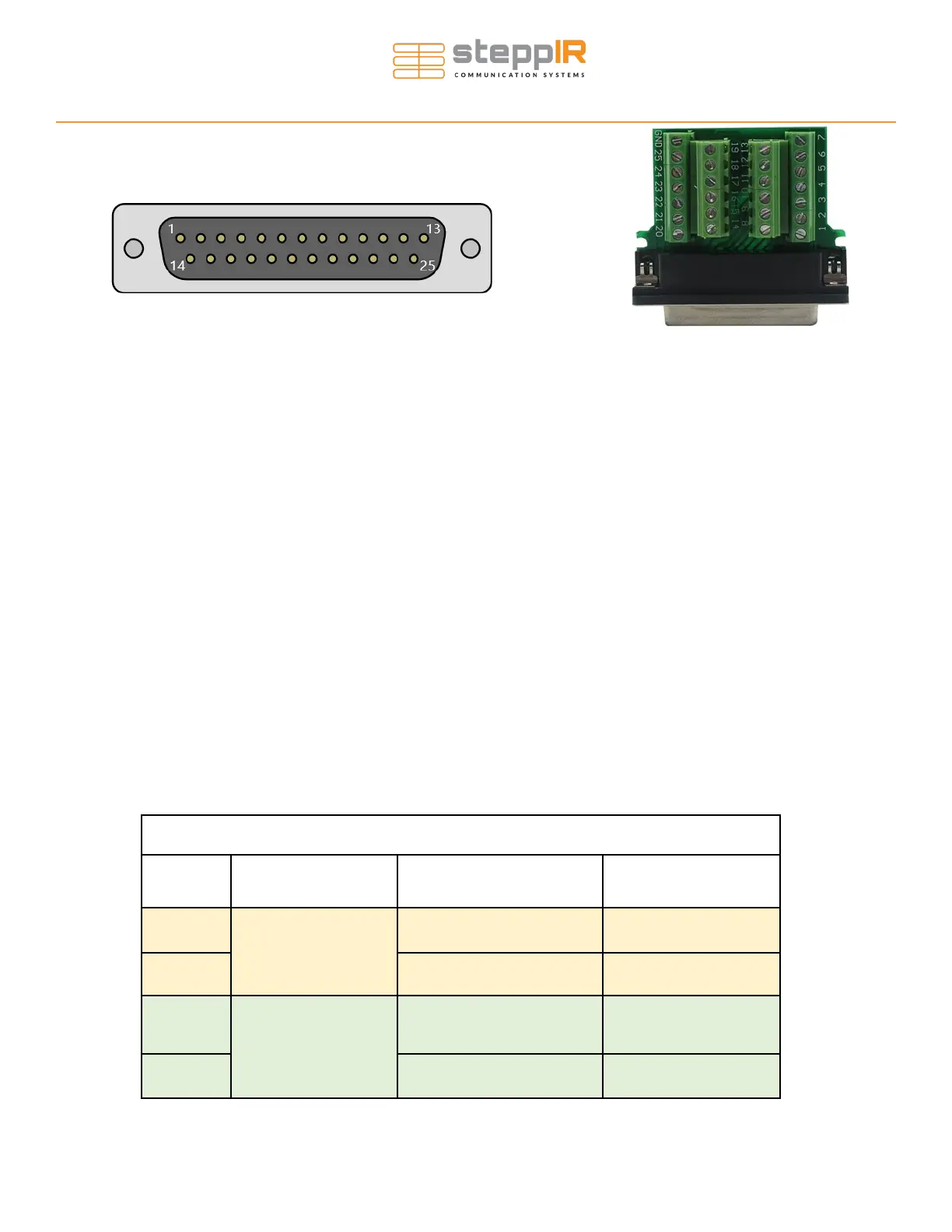
Step 2: Hold the DB25 connector so you are looking at the pins with them pointing at you or open the back
shell of the DB25 field splice. If prodding the pins directly, orient the connector so the row with 13 pins is on
top, now the upper left-hand pin is pin 1. See figure 2.11 (above) for reference. If you decide to open the
case of the connector, reference the pin number marking on the PCB (see figure 2.12 above).
Step 3: Measure the resistance between the pin pairs indicated. You only need to measure the resistance of
wires that correspond to the elements on your antenna. For example: if you don’t have the loading coil, meas-
ure the pin pairs associated with the BigIR EHU only. You should read between about 15 ohms to 30 ohms
depending on cable length between the pins listed below. Record your results in the “Results” column. (100’
is about 23 ohms).
Resistance Test Table
Pin Pair Antenna Element Expected Resistance Results (Ohms)
1-2
BigIR EHU
~ 20 Ohms
3-4 ~ 20 Ohms
5-6
80/60/40/30m Coil
~ 20 Ohms
7-8 ~ 20 Ohms
Figure 2.11
Figure 2.12
EHU/COIL WIRING TESTS