EasyManua.ls Logo

Sterling M2B+ - User Manual

Sterling M2B+
65 pages
Print Icon
To Next Page IconTo Next Page
Loading...
M2B+ Controller
M2B+ Controller
Part Number: 682.92011.00
Bulletin Number: SC1-630.8
Effective: 12/10/07
Write Down Your Serial Numbers Here For Future Reference:
_________________________ _________________________
_________________________ _________________________
_________________________ _________________________
We are committed to a continuing program of product improvement.
Specifications, appearance, and dimensions described in this manual are subject to change without notice.
DCN No. ____________
© Copyright 2007
All rights reserved.
Chapter 1: Safety 1 of 65

Table of Contents

Questions and Answers

  • F
    Franklin OlsenAug 16, 2025
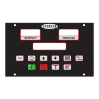
    Why won't the setpoint temperature change when I use the up or down arrow keys on my Sterling Controller?
    • S
      steven05Aug 16, 2025
      If the setpoint temperature on your Sterling Controller isn't changing when you use the up or down arrow keys, it could be due to a security lockout or remote input settings. First, check your security settings and change them to gain access to the parameters. If that's not the issue, verify that the 'Remote Input' parameter in the Secondary Menu is set to 'OFF'.
  • F
    faith47Aug 19, 2025
    What to do if the buttons on my Sterling M2B+ are not working?
    • S
      Samuel HaleAug 19, 2025
      If the buttons on the front of your Sterling Controller aren't working, there are a few potential causes. It could be due to a security password being set to lockout status, requiring you to change the security setting to access the parameters. Alternatively, the controller parameters might be set to remote function; in this case, change the parameters to local function. Lastly, excessive environmental noise could be the problem.
  • W
    William HallAug 22, 2025
    How to troubleshoot if my Sterling M2B+ Controller doesn't communicate with a remote host computer?
    • M
      Matthew RobertsonAug 22, 2025
      If your Sterling Controller isn't communicating with a remote host computer, there are a couple of things to check. First, make sure the communications board is properly installed in slot J8 on the secondary controller board. Also, verify that the 'Comm Protocol' parameter in the Secure Menu is set to the correct protocol (MOD for MODBUS® RTU or SPI).
  • H
    hamptonrobinAug 25, 2025
    What to do if the Process Temperature Alarm on my Sterling M2B+ Controller doesn't acknowledge when the Process Temperature is higher than the Setpoint?
    • J
      James SalinasAug 25, 2025
      If the Process Temperature Alarm on your Sterling Controller isn't acknowledging when the Process Temperature is higher than the Setpoint, the alarm configuration or mode might be set up incorrectly, or the alarm trip point may be incorrect. Try changing the configuration to Low, High, High/Low, or Event. Also, change the Mode to either Absolute or Deviation. Finally, adjust the value of the high or low tripping point for the alarm.
  • D
    Dr. Cynthia WilsonAug 28, 2025
    What to do if the Process Temperature Alarm on my Sterling Controller doesn't acknowledge when the Process Temperature is lower than the Setpoint?
    • D
      David DaltonAug 28, 2025
      If the Process Temperature Alarm on your Sterling Controller isn't acknowledging when the Process Temperature is lower than the Setpoint, the alarm configuration or mode might be set up incorrectly, or the alarm trip point may be incorrect. Try changing the configuration to Low, High, High/Low, or Event. Also, change the Mode to either Absolute or Deviation. Finally, adjust the value of the high or low tripping point for the alarm.
  • M
    Marissa DiazAug 31, 2025
    Why won't the setpoint change with a change of Remote Analog Setpoint value, or why does the setpoint display 0 on my Sterling Controller?
    • S
      Shelly HoganAug 31, 2025
      If the setpoint on your Sterling Controller isn't changing with the Remote Analog Setpoint value, or if it's displaying 0, the remote input might not be enabled, or the remote signal value might be incorrect. Change the value for 'Remote Input' in the Secondary Menu to SETP. Also, change the range for 'Remote Signal' to the desired setting.
  • C
    candiceleeSep 3, 2025
    How do I fix a Ramp/Soak program that does not transition to the desired setpoint on my Sterling Controller?
    • M
      Marcus GregorySep 3, 2025
      If your Ramp/Soak program isn't transitioning to the desired setpoint on your Sterling Controller, several factors could be at play. The program might have been stopped; in that case, either press the Run/Hold button on the controller or change the value of 'Prog Ramp/Soak' in the Secondary Menu to ON. It's also possible that the segment setpoint is incorrect, requiring you to change the value of 'Seg # SetPoint' to the desired temperature. Finally, the program time might be too short for the unit's heating/cooling capacity, so try changing the value of 'Seg # Time' to a longer timer period.
  • J
    Joseph JonesSep 6, 2025
    What to do if my Sterling Controller's Ramp/Soak program never stops cycling through steps?
    • C
      christophermilesSep 6, 2025
      If your Sterling Controller's Ramp/Soak program never stops cycling through steps, the Program End function is likely incorrectly configured. Change the value of 'Prog End' from LOOP to the desired action at the end of the program.
  • S
    Sydney GonzalezSep 9, 2025
    Why does my Sterling M2B+ Controller unit shut down after running through a Ramp/Soak program?
    • P
      Patrick JohnsonSep 9, 2025
      If your unit shuts down after running through a Ramp/Soak program, the Program End function is likely configured incorrectly. Change the value of 'Prog End' from OFF to the desired action at the end of the program.
  • R
    Rachel JohnsonSep 12, 2025
    Why does the last setpoint in my Sterling M2B+'s Ramp/Soak program revert back to the first setpoint?
    • M
      Michelle WardSep 12, 2025
      If the last setpoint in your Ramp/Soak program reverts back to the first setpoint, it means the Program End function is incorrectly configured. To fix this, change the value of 'Prog End' to HOLD.

Summary

Chapter 1: Safety

Safety Symbols Used in this Manual

Explanation of DANGER, WARNING, and CAUTION symbols for hazard identification.

Shipping Information

In the Event of Shipping Damage

Procedures for filing claims and obtaining authorization for damaged goods.

CHAPTER 2: FUNCTIONAL DESCRIPTION

2-2 General Description

Microprocessor-based controller for temperature control units with PID auto-tuning.

2-3 Standard Features

Key features including PID control, LCD display, sensor types, and alarms.

2-5 Panel Layout and Keypad

Description of control panel buttons, LED indicators, and LCD display layout.

LCD Messages

Explains various messages displayed on the controller's LCD screen.

Keypad

Details functions of each button on the controller's keypad.

Menu Structure

Organization of controller parameters into Primary, Secondary, and Secure menus.

2-7 Passwords and Security

Four security levels control access to setup menus and parameter changes.

CHAPTER 3: INSTALLATION

3-2 Electrical Connections

Requirements for clean power supply and wiring separation.

CHAPTER 4: BASIC OPERATION

4-2 Starting and Stopping Water TCUs

Procedures for starting and stopping water temperature control units.

4-3 Starting and Stopping Hot Oil TCUs

Procedures for starting and stopping hot oil temperature control units.

4-4 Tuning

Procedures for tuning the controller's performance.

Autotuning

Process of automatically tuning the controller for optimal performance.

Manual Tuning (Zeigler-Nichols PID Method)

Step-by-step guide for manual PID tuning.

4-5 Selecting a Local Probe

Procedure to select and configure temperature probe inputs.

Using a Remote Input Probe for Monitoring

Procedure to monitor process temperature using a remote probe.

4-6 Setting Up Cascade Control

Configuring the internal cascade control feature for multi-lag processes.

4-7 Adjusting the Automatic Venting Timer

Setting the duration for the auto vent cycle at unit startup.

4-8 Using Crash Cool

Quick cooling feature for the process.

CHAPTER 5: ADVANCED OPERATION

5-1 Using the Analog Remote Input

Accepting remote analog setpoint or flow value for control.

5-2 Retransmission Analog Signal

Transmitting analog signals for process temp, setpoint, and flow.

Setting the Analog Signal Source to FLOW

Configuring the analog signal source specifically for flow monitoring.

Using Analog Output for Heating and Cooling

Setting up analog outputs for proportional control of heating/cooling.

5-3 Using the Flow Monitor

Setting up pulsed or current input from a flow sensor.

5-4 Programming the Alarms

Setting up critical and non-critical alarms for process monitoring.

5-5 Using the Second Setpoint Function

Enabling a second setpoint via a dry contact signal.

5-6 Using the Remote Start Function

Activating the controller via a remote dry contact signal.

5-9 Using the Elapsed Time Meter

Tracking pump motor run time in hours; enabling/resetting.

5-10 Programming Ramp;Soak

Setting up a 16-segment programmable Ramp/Soak feature.

Controlling Ramp;Soak

Steps to start, hold, and resume ramp/soak operations.

Monitoring Ramp;Soak

How to view segment status and time during ramp/soak operation.

5-11 Setting the Approach Rate

Selecting up/down ramp to setpoint feature time base.

5-12 Level Input Operation (Water Units)

Handling of three-second input suppression timer for fluid level.

5-14 Adjusting the Auto Shutdown Temperature Setpoint

Setting an adjustable shutdown setpoint for the controller.

5-15 Calibrating the T;C, RTD, and V Inputs

Procedures for calibrating sensor inputs and analog input.

Calibrating the Thermocouple Input (T;C)

Steps to calibrate thermocouple sensor inputs.

Calibrating the RTD Input

Steps to calibrate RTD sensor inputs.

Calibrating the Analog Input (V)

Steps to calibrate analog voltage inputs.

5-16 Accessing the Debug Menu

Using the debug menu for troubleshooting communications and flow sensor errors.

5-17 Reloading Factory Defaults

Restoring controller to factory default settings.

5-18 Serial Communications Operation

Configuring RS232/RS485 communication links and protocols.

Port Address

Configuration of the communication port address.

Baud Rate and Data Format

Selection of communication speed and data format.

Protocols

Selection of communication protocols like MODBUS and SPI.

CHAPTER 6: TROUBLESHOOTING

6-1 Operating Mode and Error Display Messages

Explains various messages displayed during operation and errors.

CHAPTER 7: APPENDIX

7-1 Electrical Specifications

Details electrical properties, dimensions, and operating environments.

Primary Menu Parameter Table

Secondary Menu Parameter Table

Secure Menu Parameter Table

Secure Menu Parameter Table Continued

7-4 Technical Assistance

Sterling M2B+ Specifications

General IconGeneral
BrandSterling
ModelM2B+
CategoryController
LanguageEnglish