74
Reading Service Codes
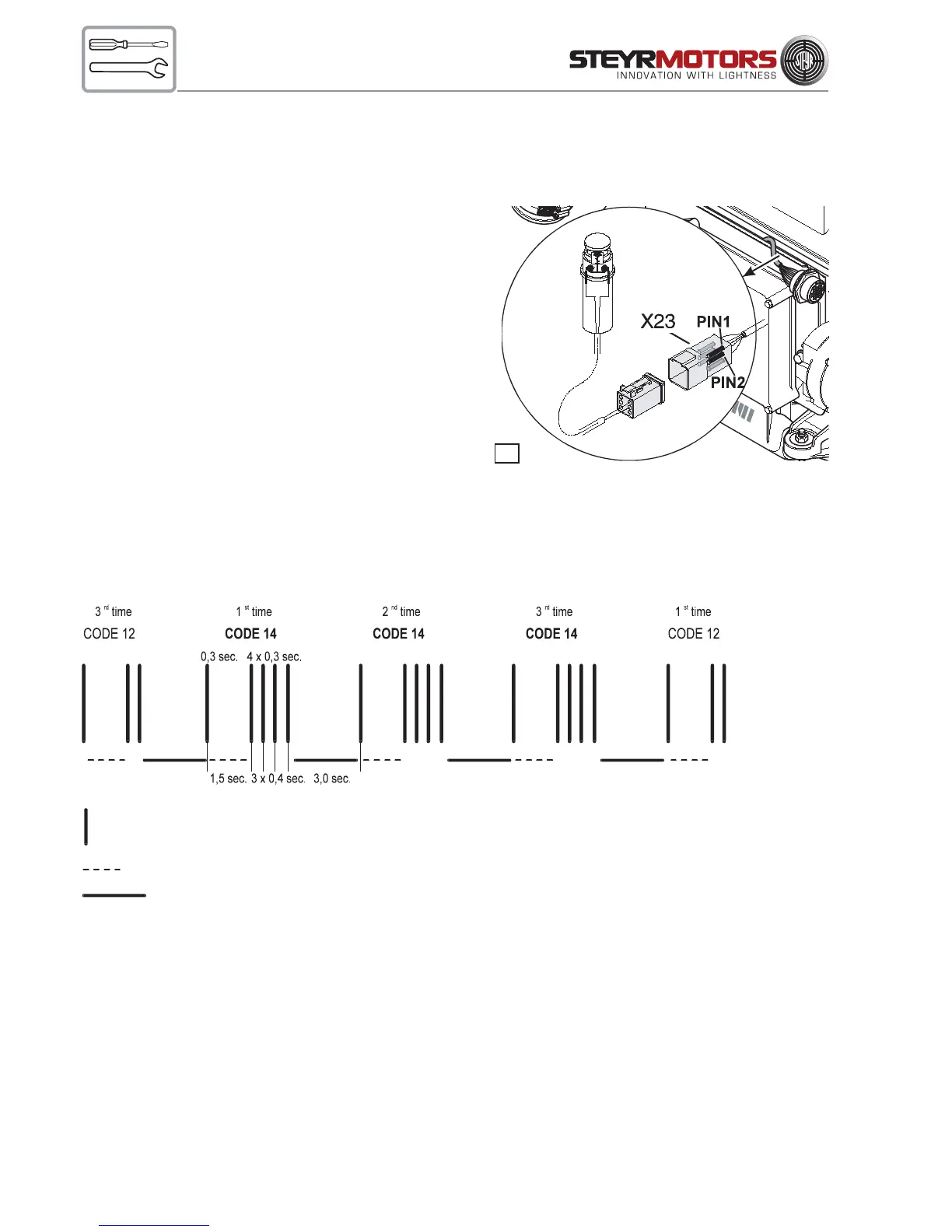
Entering and reading of stored faults via Check Engine Lamp and Diagnostic Outlet Plug (X23):
w
Needed device:
Tool VR00135/1
(normally closed push button switch)
connected to Diagnostic Outlet Plug X23.
In case this tool is not available:
Connect temporarily Pin – Pos. 1 with Pin – Pos. 2
of Diagnostic Plug X23
(before ignition is turned on at key switch)
Connect as above and turn the ignition on to enter error indica-
tion mode.
Code indication and indication sequence:
After entering the service code indication modus the Engine
Management System will display a blink code at the Check Engine Light on the dash panel.
The blinking sequence will always begin and end with control code indication # 12. Each service code will be re-
peated 3 times to assure your correct reading – see below bar code illustration.
Example sequence check engine light: Service code # 14
If more then one service code is stored in the Engine Management System the indication sequence will be continued
blinking additional stored error codes. To delete a memorized service code see description Indication and Cancella-
tion of memorized sensor and circuit faults.
For a description of the possible service codes refer to enclosed Table – Service Codes
ATTENTION:
q
To exit from Service code indication. Tool VR00135/1 must be removed (connection between
Pin 1 to Pin 2 opened) before ignition is turned ON again.
Stroke = Check Engine Light illuminated for 0.3 sec. (Light Off – period within blink sequence 0.4 sec.)
Dashed Line = interruption within code indication 1.5 sec.
Solid Line = interval interruption between service code 3.0 sec.
18