85
Description – Wiring harness instrument panels 4/6 cyl. marine engines (current version)
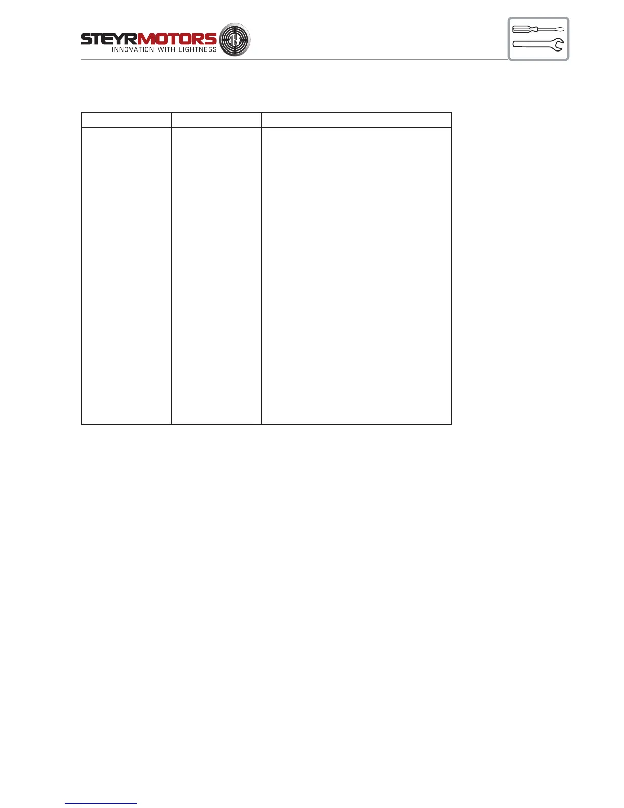
Designation Component Description
F9 fuse 10 A
J1 23-pin plug connection engine cable – instrument
cable
S1 switch ignition (red)
S2 switch start (green)
S3 switch emergency cut off (orange)
S7 switch key switch constant revolution (optional)
L1 lamp charge control
L2 lamp cel – check engine lamp
L3 lamp oil pressure/preheating conrol
P1 gauge engine coolant temperature
P2 gauge oil pressure (optional)
P3 gauge tachometer with running-time meter
H22 warning horn
E10 lighting engine coolant temperature gauge
E11 lighting oil pressure gauge (optional)
E12 lighting tachometer gauge
X8 1-pin plug connector illumination switch
X24 8-pin plug connector STEYR MOTORS – display
Z1 splice battery +
Z2 splice battery –
Z3 splice ignition (+)
Z4 splice key switch constant revolution
24 V interm. cable charge indicator