_____________________________________________________________________________________
STI S.r.l. – Via Dei Caravaggi 15, 24040 Levate (BG) – ITALY www.imi-critical.com
Manual 4054 – rev.00 02/2021 – DT2 - 10 -
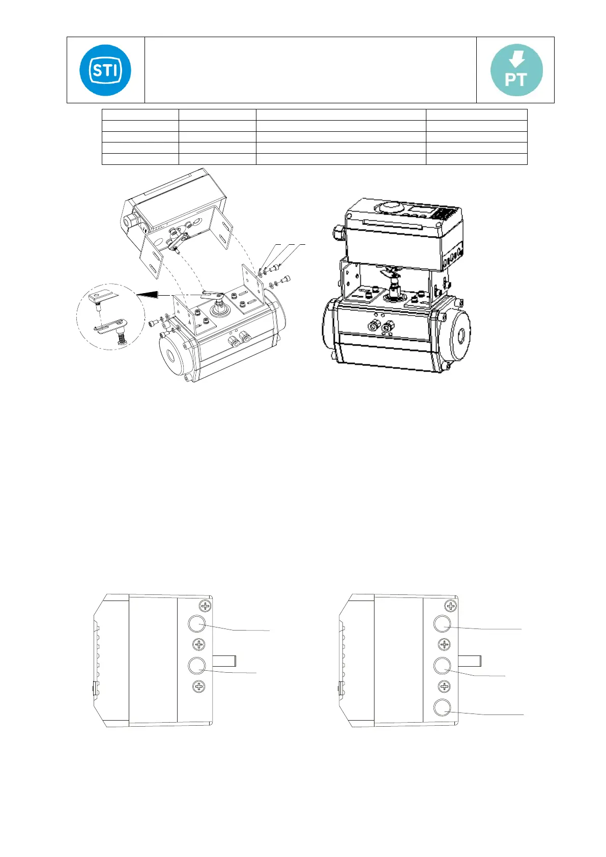
Figure 5-b
The installation steps as follow:
- Attach the Bracket 2 (6) to the positioner with socket cap screws (3), elastic washers (2) and washers (1).
- Attach the feedback lever (4) to the shaft and fix with the set screw (5).
- Attach the Bracket 1 (7) to the actuator with socket cap screws (10), elastic washers (11) and washers (12).
- Attach socket cap screws (9) to the U shape feedback lever (8) and attach the U shape feedback lever (8) to
the actuator.
- Put the positioner carefully on the actuator. The pin of the feedback lever (4) should be in the through of the U
shape feedback lever (8). Adjust the height of the positioner, lock screw on the pin of the feedback lever (4)
and fix the positioner with socket cap screws (3), elastic washers (2) and washers (1). Adjust the rotate angle
of the feedback lever so that it complies to the requirement in 4.2.1
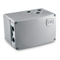
4.5 Pneumatic connection
Pneumatic Connections is on the right of positioner, positioner provides two kind of connection types: G1 / 4 and NPT
1/4 (refer to ordering data). See the specific marks on the housing and choose correct type according to the marks.
Figure 6: Pneumatic Connection