_____________________________________________________________________________________
STI S.r.l. – Via Dei Caravaggi 15, 24040 Levate (BG) – ITALY www.imi-critical.com
Manual 4054 – rev.00 02/2021 – DT2 - 8 -
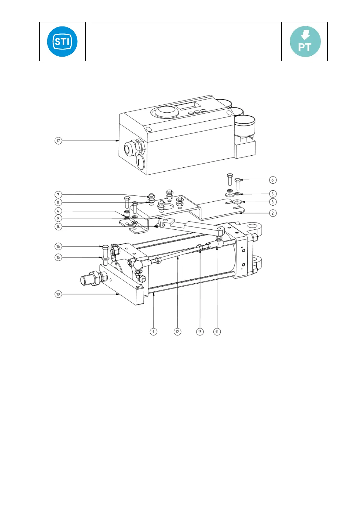
4.3 Assembly for linear actuator
For linear actuator SC63 with lever feedback:
Figure 4-a
The positioner is installed on the side of the actuator. Through the adjustable feedback lever actuator connected with
actuator’s putting lever (as Figure 4-a), the installation steps as follows:
- Fix the support plate [# 2] on the actuator through the four screws [# 6+4+3].
- Fix the positioner [# 17] on the plate through the four screws [# 7+8].
- Connect the lever [#9] to the positioner shaft and insert the screw [#14] into the lever on the side of the lever.
- Move the actuator shaft to 50% to the stroke, rotate the lever [#9] perpendicular to the support plate, if
necessary adjust the length of the treaded rod [#12] unloosing the nuts [#13], rotating the bar and fixing again
the nuts.
- Adjust the rotate angle of the feedback lever so that it complies to the requirement in 4.2.1.and fix tight the
screw [#14].
- Move the actuator shaft from 0% of the stroke to 100% checking that there is not mechanical interference of
the linkage components.
For actuators with motion converter feedback linkage:
Positioner installed on the side of the actuator. Through the motion converter STI model MC, connected with actuator’s
shaft with rod and cam; the installation steps are the following
- Fix the support [# 1] on the motion converter with the four screws [# 3+455]