_____________________________________________________________________________________
STI S.r.l. – Via Dei Caravaggi 15, 24040 Levate (BG) – ITALY www.imi-critical.com
Manual 4054 – rev.00 02/2021 – DT2 - 11 -
Installation Steps:
1. Connect to the output of the DigitalTrak2 smart positioner to the input of the actuator.
2. Connect the IN port of DigitalTrak2 smart positioner with the air supply. The compressed air through the
positioner must be filtered and regulated.
Air requirements:
a) Air pressure must be 0.14 ~ 0.7 MPa, depending on the actuator.
b) Air supply must be clean dry air without visible oil steam, oiil or another liquid / vapor.
c) Air supply must be no significant corrosion air, steam and solvents.
d) Size and density of particulates is Class 4, oil concentration Is Class 4.
e) The air dew point under work pressure should be at least 10 ℃ lower than its work positioner environment
temperature.
4.6 Electric connections
Electrical connections should be strictly in accordance with the connection diagram, should be firmly secured, and not
be loose.
Cable connector has to be a standard waterproof connector. Outer diameter of the signal cable should be at least 8mm
and the connector cover should be locked when installing to avoid IP protection level.
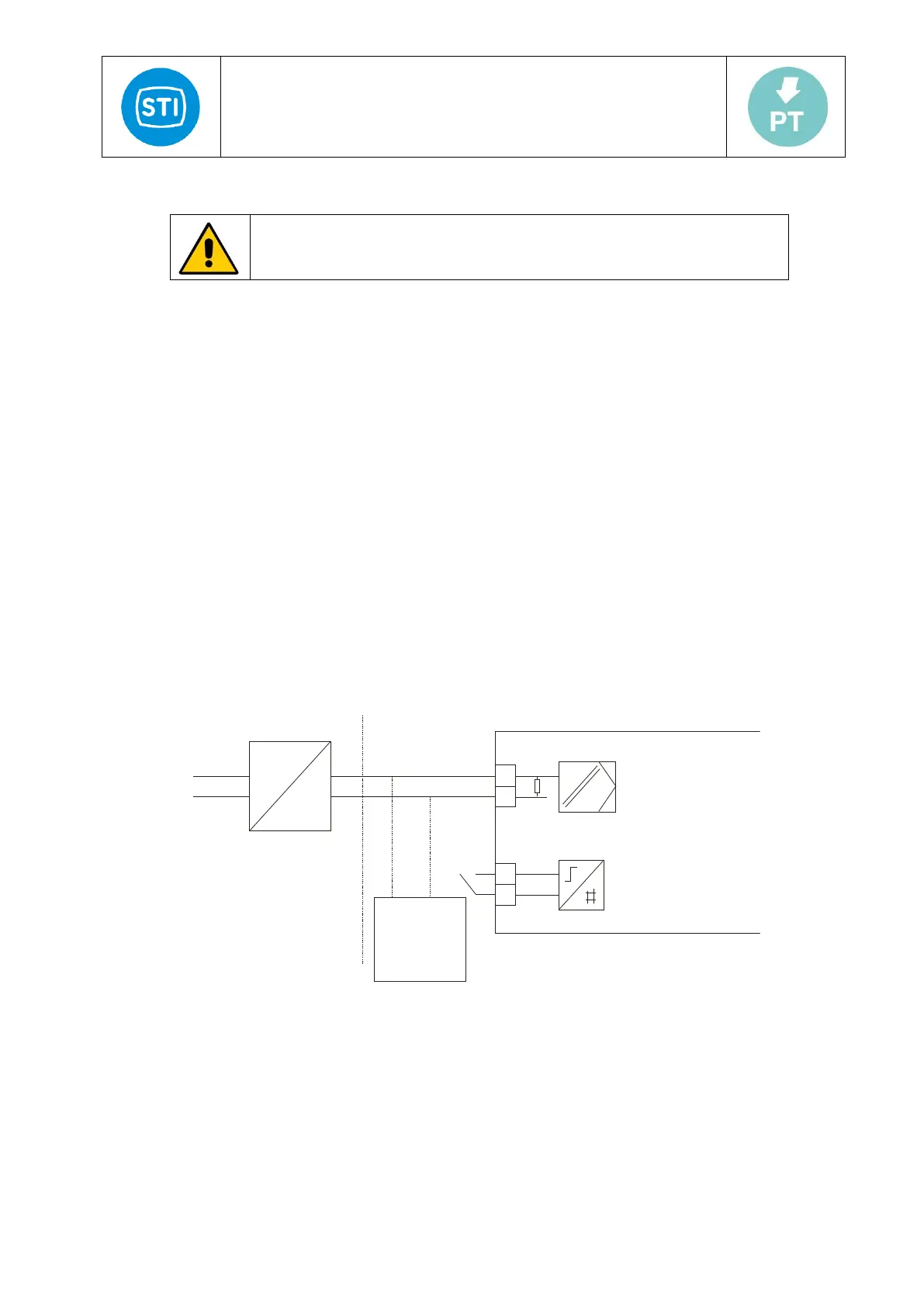
4.6.1 Input electric connection (Figure 6)
Type: Loop Power Supply system
Input signal: 4-20mA
The min. working current: 3.8mA DC
Input impedance: 455Ω @20mA (without HART), 575Ω @20mA (with HART)
Figure 7: Electric input connection
4.6.2 Analog feedback module electric connection (Figure 8):
Feedback signal type: Two-wire system, 4÷20mA
Temperature influence: ≤100ppm/°C
Working range: 3.6 ÷ 20.5 mA DC
Precision: ≤0.1%
Working voltage: 12÷35V DC