_____________________________________________________________________________________
STI S.r.l. – Via Dei Caravaggi 15, 24040 Levate (BG) – ITALY www.imi-critical.com
Manual 4054 – rev.00 02/2021 – DT2 - 7 -
4. ASSEMBLY
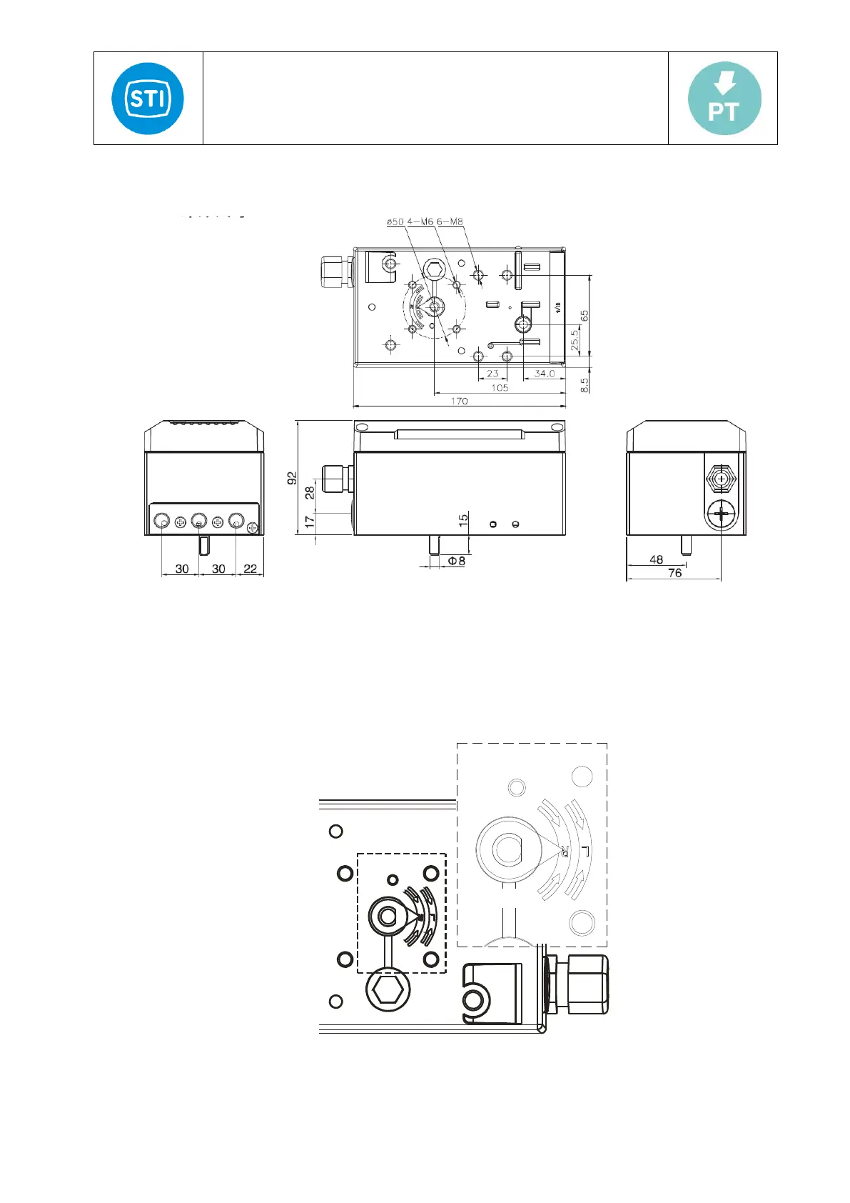
4.1 Dimensional drawings
Figure 2: Dimensional drawing
4.2 Installation
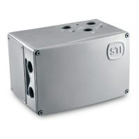
To install correctly the rotate angle of the positioner stem should comply to the required reading angle range. Figure 3-a
shows the positioner feedback indicator and the arrow marking indicator’s rotating range. Solid line shows the middle
position of the indicator (when uninitialized, the LCD feedback value should be around 50.0 and the bottom row
displays NOINIT). The two dotted lines show the limit positions of the feedback rotating range in normal status.
Figure 3