_____________________________________________________________________________________
STI S.r.l. – Via Dei Caravaggi 15, 24040 Levate (BG) – ITALY www.imi-critical.com
Manual 4054 – rev.00 02/2021 – DT2 - 22 -
38. YDIR: Zero position
With this parameter you can assign the zero position of the display to the zero position of the valves and fittings. It
also allows you to select the direction of rotation of the sensor shaft (looking at the open housing).
39. YCDW: Value for tight closing, bottom
40. YCUP: Value for tight closing, top
With this function the valve can be driven to the seat with the maximum actuating force of the actuator (continuous
contact of the piezo-valves).
The tight closing function can be activated on one side or for both limit positions.
The tight closing function can be activated when the setpoint is below the value set with parameter “YCDO” or
above that set with parameter “YCUP”.
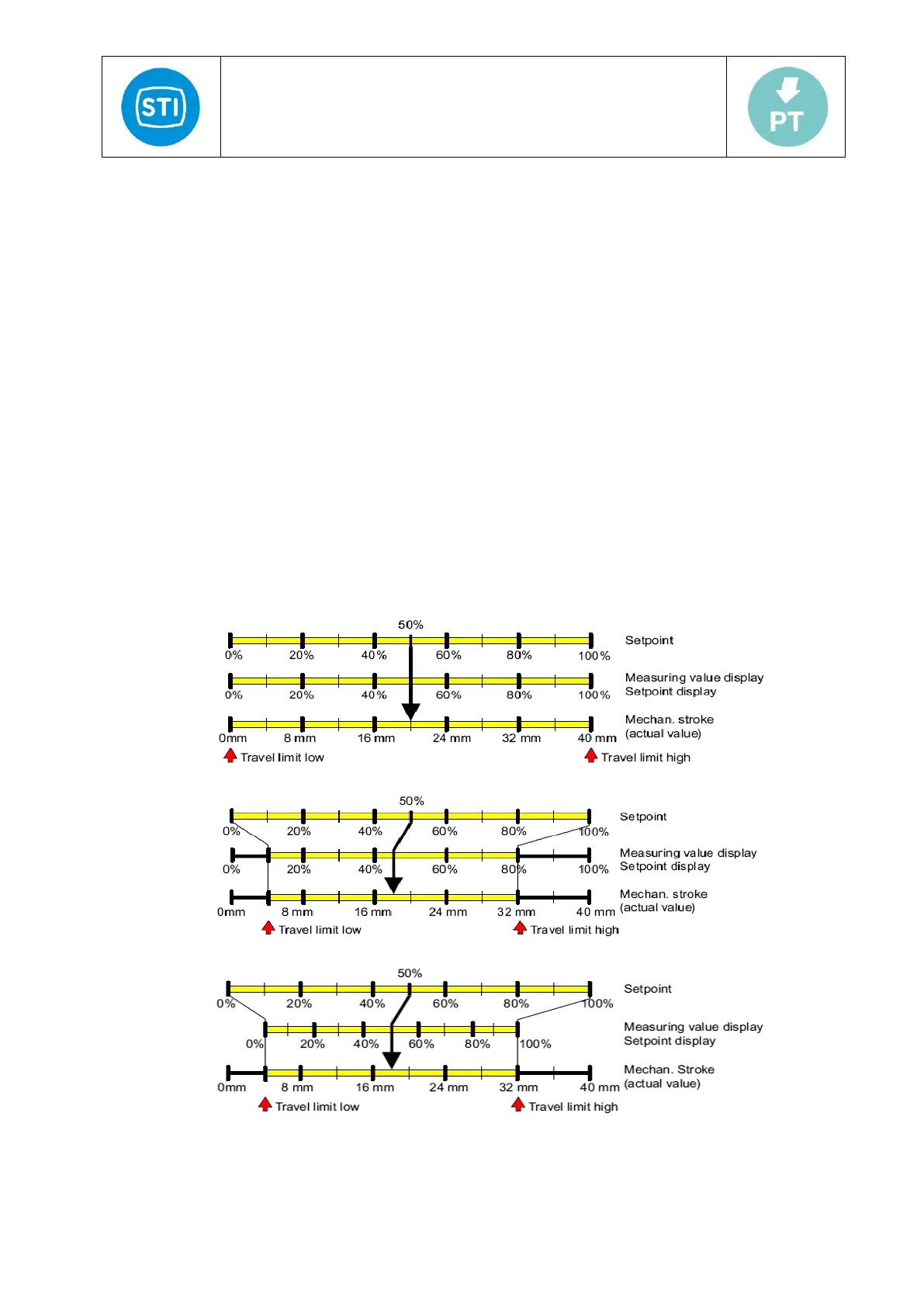
41. YNRM: Manipulated variable standardization
Using the "YA" and "YE" parameters, you can limit the manipulated variable. This limitation causes two different
scaling types, MPOS or FLOW, for the digital display and for the position feedback through the current output. See
the figure below.
The MPOS scaling type shows the mechanical position from 0 to 100% between the hard stops of the initialization.
The position is not influenced by the "YA" or "YE" parameters. The parameters "YA" and "YE" are shown in the
MPOS scale.
The FLOW scale is a scaling from 0 to 100% over the range between the "YA" and "YE" parameters. Over this
range, the setpoint w is also always 0 to 100%. This results in a more or less flow-proportional display and position
feedback "AO". The flow-proportional display and position feedback" AO " also results from the use of valve
characteristics.
In order to calculate the regulation difference, the setpoint in the digital display is also shown to the corresponding
scale.
The following uses the example of an 80-mm linear actuator to illustrate the dependence of the stroke on the
scaling as well as the parameters "YA" and "YE".
Fig.13: YNRM = MPOS or YNRM = FLOW; default: YA = 0 % and YE = 100 %
Fig.14: Example: YNRM = MPOS with YA = 10 % and YE = 80 %
Fig.15: Example: YNRM = FLOW with YA = 10 % and YE = 80 %