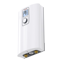
INSTALLATION
Alternative installation methods
ENGLISH
www.stiebel-eltron.com DCE-X Premium | 15
Break out the required aperture in the back panel for the
power cable (for positions, see chapter "Specification/ Di-
mensions and connections"). Deburr any sharp edges with a
file.
Cut a hole in the cable grommet to fit the selected connecting
cable. Fit the cable grommet.
Install the appliance and connect the power cable to the
mains terminal as described in chapter "Installation/ Stand-
ard installation on finished walls".
13.3 Electrical connection on unfinished walls with
short power cable
If the power cable is not quite long enough, you can install the
mains terminal in the appliance a little closer to the aperture.
D0000073648
1
1 Cable grommet
Reposition the mains terminal from the top to the bottom. To
do so, unclip the mains terminal by pushing it firmly to the
left and pulling it forwards. Clip the mains terminal in at the
bottom by pushing it inwards and to the left until it clicks
into place.
13.4 Electrical connection from the side on finished
walls
Cut and break out the required aperture in the appliance
back panel and appliance cover for the power cable (for po-
sitions, see chapter "Specification/ Dimensions and connec-
tions"). Deburr any sharp edges with a file.
Install the appliance and connect the power cable to the
mains terminal as described in chapter "Installation/ Stand-
ard installation on finished walls".
13.5 Water installation on unfinished walls
You will need the appropriate accessories to carry out the in-
stallation. The installation kit for water installation on unfinished
walls contains:
- 2 x grommets to seal the apertures in the appliance back
panel.
- Strainer with sealed edge for installation on the 45°twin
connector.
- Flat gasket
Preparation
D0000073660
Insert and seal the 45°twin connectors.
To break out the apertures in the appliance back panel, you will
need to remove the function module from the back panel.
1.
4.
5.
2.
3.
D0000077971
Undo the screw and disengage the locking tab.
Push the function module on the back panel gently
backwards.
Remove the function module from the appliance back panel
by pulling it slightly forwards and lifting it out.
Push/break out the required apertures for the water connec-
tions in the back panel from behind (for positions, see chap-
ter "Specification/ Dimensions and connections"). Deburr any
sharp edges with a file.
Fit the function module in reverse order onto the appliance
back panel until it clicks into place.
Secure the function module with the screw.
 Loading...