www.stiebel-eltron.com LWZ304-404 SOL | 21
INSTALLATION
Installation
5.9.2 Cable routing
Push all connecting cables and sensor leads through one of
the cable entries located at the top of the back panel of the
cylinder module.
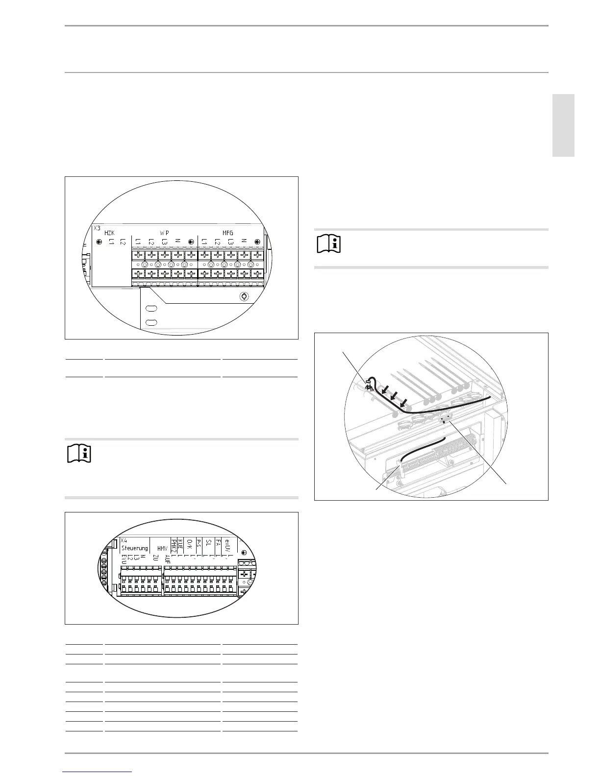
5.9.3 Terminals X3: Heat pump (compressor) and electric
emergency/booster heater
D0000053528
WP Heat pump (compressor) PE, L1, L2, L3, N
MFG Electric emergency/booster heater of
the multi function assembly
PE, L1, L2, L3, N
For optimum function, connect all three stages of the electric
emergency/booster heater.
5.9.4 Terminal X4
Note
Install additional contactor relays if more than one exter-
nal heating circuit pump will be connected at the heating
circuit 2 pump terminal "P-HK2". Use our relay box (see
chapter "Appliance description/ Further accessories").
D0000038970
Steuerung Control PE, L1, N
HMV Mixer N, CLOS, OPEN
P-HK2 Heating circuit 2 pump PE, N, L
EVU Contact for Power-OFF command by
the power supply utility (option)
KUE Cooling (option) L, N
O/K Oven / fireplace (option) L, L'
P-S Solar circuit pump (option) L, N
SL Quick-acting air vent valve (option) L, L'
FA Window open (option) L, N
The SL terminal is a 230V input for activating ventilation by means
of a pushbutton.
The FA terminal is a 230V output for switching an automatically
controlled window with passive cooling, for example.
The KUE is a 230V output for activating the cooling circuits.
5.9.5 Power-OFF
Connect the signal from the power time switch to the X4/power
supply terminal (see chapter "Commissioning/ Power-OFF").
5.9.6 Special tariff
Note
For special tariff connections, ensure that terminal X4/L1
(extractor fan) is always 'live'.
5.9.7 Connecting internal cables/leads
The cylinder temperature sensor and the power cable for the sig-
nal anode are routed out of the function module at the top l.h.
side. All cables/leads are identified accordingly.
1
2
3
26_04_01_0561
1 Anode connection at the cylinder
2 Terminal bracket X24
3 Earth block X32
Connect the signal anode at the top of the cylinder. Route
the anode cable through the groove cut into the thermal
insulation.
Connect the cable from the terminal bracket X24 to the earth
block X32.
 Loading...


