22 | LWZ304-404 SOL www.stiebel-eltron.com
INSTALLATION
Installation
1
2
26_04_01_0328
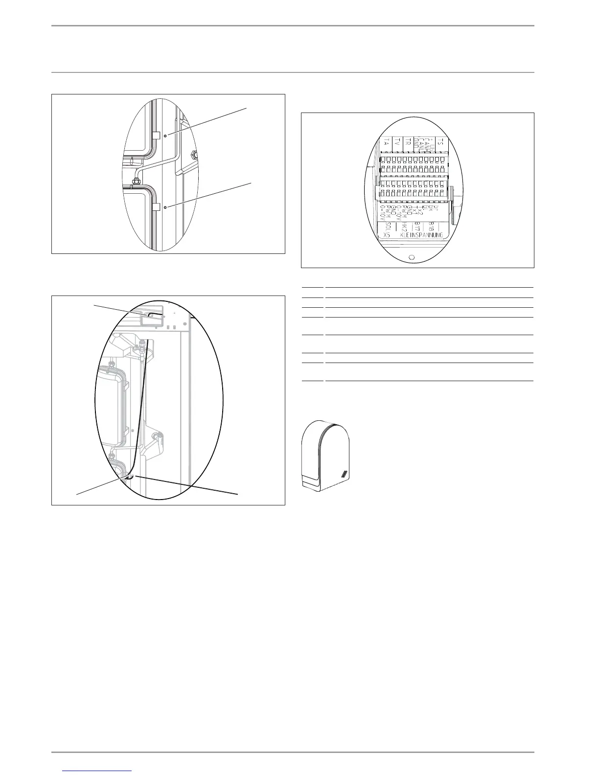
1 Sensor well for the cylinder temperature sensor (economy
mode/buffer mode)
2 Sensor well for the cylinder temperature sensor (Comfort)
1
2
3
26_04_01_0556
1 Aperture in the thermal insulation for the sensor lead
2 Clamp (prevents the cylinder temperature sensor from slip-
ping out)
3 Cylinder temperature sensor inside the sensor well
Insert the cylinder temperature sensor into the cylinder
sensor well. Ensure that the cylinder temperature sensor is
seated correctly.
The sensors integrated in the appliance, the sensors supplied and
the outside temperature sensor are PTC and PT1000 sensors. The
collector sensor supplied is a PT1000 sensor.
5.9.8 Connecting sensors
D0000038971
TA Outside temperature sensor
TV Mixer circuit flow temperature sensor
TR Room temperature sensor
TS Solar temperature sensor
SOL Control connection for the solar circuit pump (control with 0-10V or
PWM signal)
HK2 Control connection for the pump of heating circuit 2 (control with
0-10V or PWM signal)
B17 DHW sensor (unused)
B18 Dome/integral sensor embedded in the cylinder foam (has no function
for this appliance)
Outside temperature sensor AFS2
The outside temperature sensor should be freely
exposed to the elements. Never fit it above win-
dows, doors, light wells or air ducts, and never
subject it to direct insolation.
Install the outside temperature sensor on a north
or north-east facing wall on the exterior side of a
heated room.
Never install the outside temperature sensor near an exhaust air
discharge or any other influencing factors (e.g. drier discharge).
The minimum height above the ground is 2.5m, and minimum
side clearance to windows and doors is 1m.
Remove the cover of the sensor enclosure.
Secure the sensor enclosure to the wall using the screw
provided.
Route the sensor lead through the cable entry in the back
panel of the cylinder module.
Connect the sensor lead to terminal X5-TA.
Connect the sensor lead to the outside temperature sensor.
Place the cover on the sensor enclosure so that it clicks audi-
bly into place.
Room temperature and solar sensor
If planned as part of the system configuration, install the sensors
according to the sensor installation instructions.
Route the sensor lead through the cable entry in the back
panel of the cylinder module.
Connect the room temperature sensor to X5-TR.
Connect the solar sensor to X5-TS.
 Loading...


