8.3.3 Checking the flow rate (during heat pump commissioning)
Check the flow and return temperatures of the heat source. For
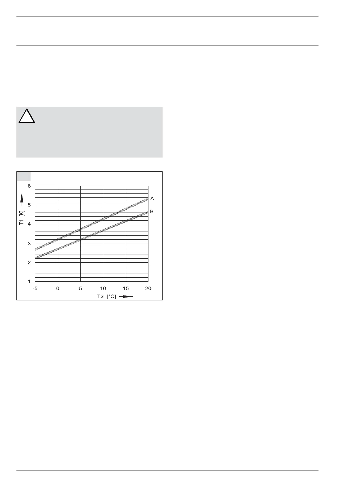
this, determine the temperature differential by measuring the
temperature under the thermal insulation on both flow and
return pipes of the heat pump. The diagram (Fig. G) shows the
temperature spread at the nominal flow rate.
!
Risk of damage!
At the WPM II, set parameter 12 (source) in the
commissioning list to "Ethylene glycol", otherwise the
frost stat would stop the heat pump at temperatures
below 7 °C. The source inlet temperature can be
checked on the display of the WPM II under the Info
Temp. system parameter.
G
Temperature spread at nominal flow rate
C26_03_01_0834
A Brine = heating flow 35 °C
B Brine = heating flow 50 °C
T1 Temperature differential
T2 Source inlet temperature
8.4 Installation of the heat consumer system
8.4.1 Implement the heat consumer system (heating circuit)
in accordance with current technical rules. For safety equipment
in heating systems, consult the DIN EN 12828.
Protect the heating water lines against frost and moisture (only
in case of external installation). Protect flow and return lines
in external installations with an adequate amount of thermal
insulation against frost and by routing them inside a conduit
against moisture
(see Fig. D).
Maintain the required insulation thickness in accordance with the
Heating System Order [or local regulations].
The integral frost protection control (inside the heat pump), that
automatically starts the circulation pump in the heat pump circuit
at + 8 °C and thereby safeguards circulation in all water-bearing
components, offers additional frost protection. The heat pump is
started automatically no later than when the temperature inside
the buffer cylinder drops below + 5 °C.
Prior to connecting the heat pump, check the heating system for
leaks, flush it thoroughly, fill and carefully vent it.
When filling the system with heating water, observe VDI 2035,
sheet 1 [or local regulations]. In particular, this means that
— during the service life of the system, the total of the fill and
top-up water must not exceed three times the nominal volume
of the heating system,
— the total alkaline earths in the water must be < 3.0 mol/m³,
— the total water hardness must be < 3 mmol/l. Soften the water,
if the above conditions are not met.
Generally soften the heating water, if the specific system volume
> 20 l/ kW output (e.g. systems with buffer cylinder).
Ensure the correct connection of the heating flow and return.
Fit the thermal insulation in accordance with local regulations
appertaining heating systems.
8.4.2 Buffer cylinder
A buffer cylinder is recommended to ensure a trouble-free heat
pump operation. The buffer cylinder provides hydraulic separation
of the volume flow in the heat pump circuit and the heating circuit.
The flow rate in the heat pump remains constant if, for example,
the flow rate in the heating circuit is reduced by thermostatic
valves.
8.4.3 Circulation pump (cylinder primary pump)
When using a buffer cylinder, observe the pressure drop of the
evaporator, of the connecting lines, bends, valves etc. in sizing the
circulation pump to be installed.
8.4.3 Circulation pump (heating circuit pump)
Where no buffer cylinder is used, size the circulation pump on the
heating side taking the condenser pressure drop into consideration.
The flow rate at 'T = 10 K (see "Specification") of the heat pump
must be assured under all operating conditions of the heating
system through the installation of an overflow valve.
10 | WPF 20/27/40/52/66 www.stiebel-eltron.com
INSTALLATION
INSTALLATION

 Loading...


