11 Troubleshooting
N
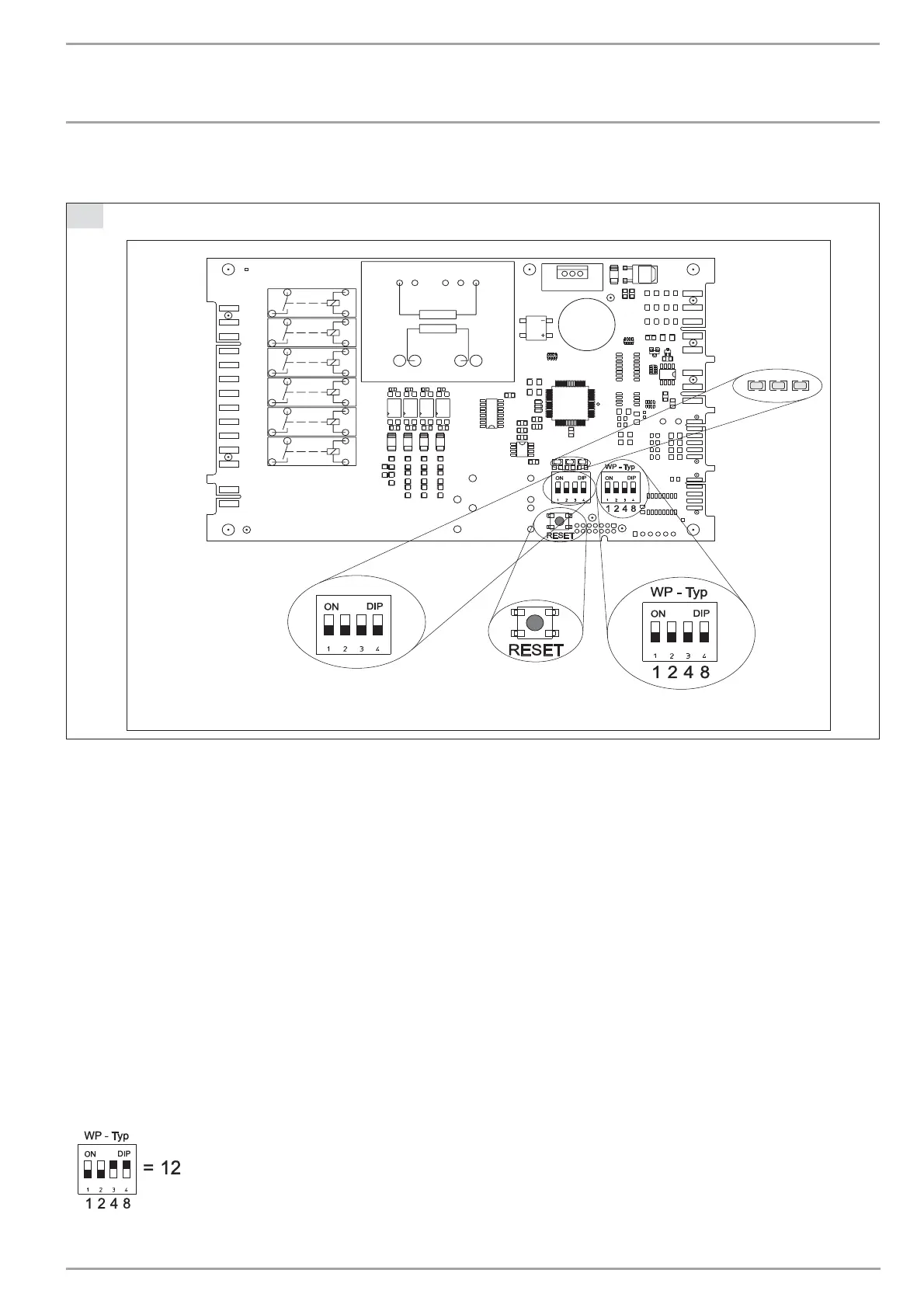
Checking the IWS settings
BA
3
2
1
4
C26_03_01_0661
1 LEDs
2 DIP switch (S1)
3 Reset button
4 DIP switch (heat pump)
The control panel with the "Internal heat pump controller" (IWS II)
becomes accessible after removing the front hood. The following
list the adjustments of the IWS II required for the WPF:
DIP switch (heat pump)
The DIP switch (heat pump) enables the pre-selection of the
various compressor systems. Subject to the system heat pump
type, for the WPF this was set to 12 at the factory.
If the WPF is to be operated as a module with another WPF, this
setting (heat pump) remains at 12.
Please check whether the DIP switch (heat pump) is set
correctly.
The correct position of the slide switch can also be checked on
control level 3 on the WPM II. The display should indicate a C under
parameter "Type IWS".DIP switch (S1)
Switches 1 and 2 have no relevance to the WPF.
Position switch 3
Switch ON : SERVICE
Corresponding compressors (defaulted by the DIP switch setting
(heat pump)) are started in intervals of one second.
Position switch 4
Switch ON : STAND-ALONE operation
Should the WPM II heat pump manager develop a fault, the heat
pump can, in emergencies, be operated in stand-alone mode.
In this operating mode, there is no communication with the
WPM II. The system regulates to a fixed set valve: the heat pump
starts at 50 °C and stops at 55 °C. For this, 230 V must be applied
to terminal X4/2, and a temperature sensor TF 6 (part no.: 165342)
must be connected as return sensor to terminals X2/4 and 5.
Insert the sensor into the sensor well at the heating circuit return
(see Fig. A)
. The operating mode is indicated by the r.h. green LED.
INSTALLATION
MAINTENANCE
17 | WPF 20/27/40/52/66 www.stiebel-eltron.com

 Loading...


