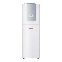
7.1 Standard delivery
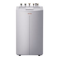
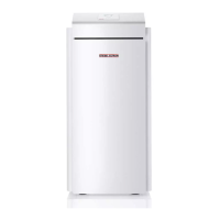
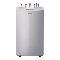
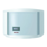
Heat pumps are delivered in two shipping units.
Designation Part no.
Standard heat pump device
Casing parts 223384
7.2 Accessories
Designation Part no.
Heat pump manager with wall mounting enclosure, WPMW II 185450
Heat pump manager as control panel mounted version, WPMS II 185451
Mixer module with wall mounting enclosure, MSMW 074012
Mixer module as control panel mounted version, MSMS 074011
Cylinder SBP 700 E 185459
Cylinder SBP 700 E SOL 185460
Kit WPVB 227760
Heating system remote control FE 7 185579
Contact sensor AVF 6 165341
Immersion sensor TF 6 165342
Heat transfer medium (concentrate) (30 litre can) 161696
8 Installation
8.1 Transport
To protect the equipment against damage, transport it vertically
inside its packaging. Storage and transport at temperatures below
– 20 °C and in excess of + 50 °C are not permissible.
In the top of the frame are four holes for fitting lifting eyes M 12
where the equipment can be lifted.
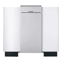
The casing parts are delivered in a separate package, and these
are fitted to the device at the place of installation.
8.2 Positioning
8.2.1 General
Level the device horizontally by adjusting the equipment feet.
To prevent the heat pump from being damaged by frost in case of
external installation, fit and electrically connect the contact sensor
AVF 6 (part no.: 165341) into the heating return as frost protection.
Electrical connection and sensor installation, see chapter 9.
Maintain the following minimum clearances to adjacent
surfaces:
— to the sides 300 mm
— in front 1500 mm
— upwards 100 mm
— The clearance to the back is subject to the installation and
installation location.
8.2.2 External installation
We recommend foundations as base for the device
(see Fig. D)
.
Route all supply lines inside a conduit that is free from frost
(protective pipe).
Protect the connection area at the back panel against all weather
and solar influences.
8.2.3 Internal installation
The room where the WPF is to be installed must meet the following
conditions:
—Load-bearing floor. For the weight of the WPF, see
"Specification".
— For a quiet heat pump operation on floating screeds, recess the
screed and the anti-vibration insulation around the installation
location
(see Fig. C)
of the heat pump.
— The room must not be subject to a risk of explosions arising
from dust, gases or vapours. Never allow the floor area and the
volume of the installation room to be less than the minimum
values listed in the table.
Type Volume Floor area
WPF 20
14 m³ 5 m²
WPF 27
16 m³ 7 m²
WPF 40
23 m³ 9 m²
WPF 52
28 m³ 11 m²
WPF 66
33 m³ 13 m²
— When installing the WPF in a boiler room together with other
heating equipment ensure, that the operation of other heating
equipment will not be impaired.
8.2.4 Sound emission.
Never install the heat pump immediately below or adjacent to
bedrooms. Insulate pipes through walls and ceilings against
structure-borne noise transmission.
6 | WPF 20/27/40/52/66 www.stiebel-eltron.com
INSTALLATION
INSTALLATION
 Loading...
