12 Specification
12.1 Standard control
O
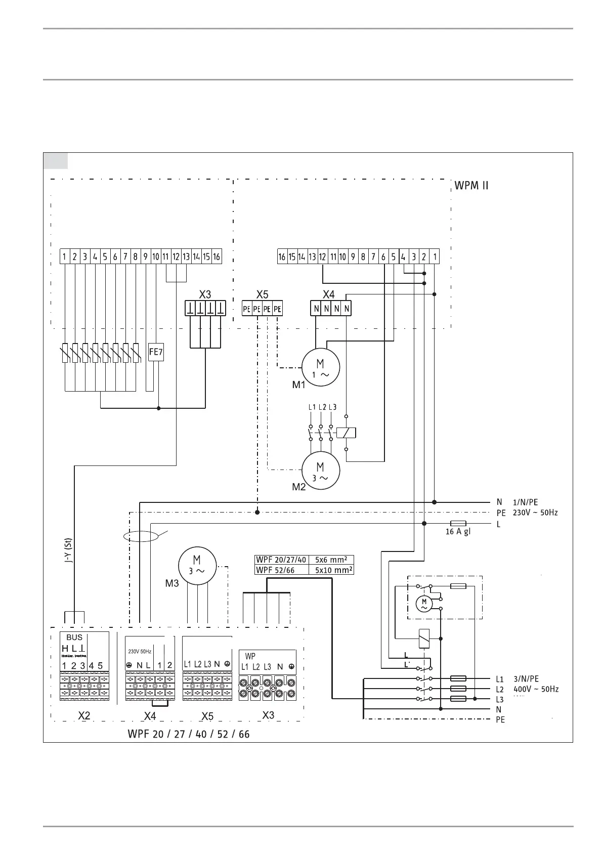
Power connection diagram for heat pumps WPF 20 / 27 / 40 / 52 / 66 with heat pump manager WPM II
C26_03_01_0800
Outside temp. semsor
Flow temp. sensor
Return temp. sensor
DHW temp. sensor
HS 2 sensor
Source temp. sensor
Mixer temp. sensor
Analog output
1 FE 7
2 FE 7
BUS H
BUS L
BUS -
BUS +
DCF
DCF
Solar
Mixer -
Mixer +
HS 2
HS 2
DHW circ. pump
DHW
Heating circuit 2
Heating circuit 1
Source
Buffer 2
Buffer 1
Pumps L
EVU L'
Mains L
Mains N
Control phase L' with
power-OFF periood
Time switch for power-OFF periods
Supply from the
domestic meter
3x1.5 mm
2
2x2x0.8
Sensor
Brine
pump
(Mains)
Heat pump
electricity
meter
Ext. control.
(Mains) (Mains)
X2
X1
M1 Circulation pumps (max. 2 A gl)
Supply from the domestic meter
M2 Circulation pump (three-phase)
Supply from the heat pump electricity meter
M3 Circulation pump (three-phase)
Supply from the heat pump electricity meter
INSTALLATION
TROUBLESHOOTING
19 | WPF 20/27/40/52/66 www.stiebel-eltron.com

 Loading...


