www.stiebel-eltron.com 15
rate
-
floor area
-
floor area
-
l m² m²
WPL 15 AS 700 16 21 3x70 21 2x70
WPL 15 ACS 700 16 21 3x70 21 2x70
WPL20A 1000 29 28 4x70 32 3x70
WPL20AC 1000 29 28 4x70 32 3x70
WPL 25 A 1000 29 28 4x70 32 3x70
WPL 25 AS 1000 29 28 4x70 32 3x70
WPL 25 AC 1000 29 28 4x70 32 3x70
WPL 25 ACS 1000 29 28 4x70 32 3x70
WPL 15 AS No 100 100 Yes
WPL 15 ACS No 100 100 Yes
WPL20A No 100 100 Yes
WPL20AC No 100 100 Yes
WPL 25 A No 100 100 Yes
WPL 25 AS No 100 100 Yes
WPL 25 AC No 100 100 Yes
WPL 25 ACS No 100 100 Yes
Install the open heating circuit(s) in the lead room (room
where the external programming unit of the heat pump con-
trol unit is installed, such as in the living room). The individ-
ual room can then be controlled either with the external pro-
gramming unit or indirectly by adjusting the heating curve or
the room influence.
Fully open the heating circuit(s) in the lead room.
Close all other heating circuits.
If an overflow valve has been installed in the heating system,
fully close this overflow valve in order to determine the mini-
mum flow rate.
In combination with a hydraulic module, cylinder and hydraulic
module or integral cylinder:
Under menu item "COMMISSIONING/ HEATING" the param-
eter "HEATING CIRC PUMP RATE" (heating circuit pump rate)
such that the minimum flow rate required for system opera-
tion is assured (see chapter "Specification/ Data table").
If the appliance is operated on its own with a WPM:
Set the heating circuit pump so that the minimum flow rate
required to operate the system is safeguarded.
The current flow rate can be called up in the menu "INFO/ HEAT
PUMP INFO/ PROCESS DATA" under "WP WATER FLOW RATE".
10.8.2 Minimum flow rate for systems with a buffer cylinder
When using a buffer cylinder, in menu "SETTINGS/ HEATING/
STANDARD SETTINGS", set parameter "BUFFER OPERATION" to
"ON".
In combination with a hydraulic module, cylinder and hydraulic
module or integral cylinder, and with spread control disabled:
In menu "COMMISSIONING/ HEATING", set parameter "HEAT-
ING CIRC PUMP RATE" so that the nominal flow rate required
for system operation is assured (see chapter "Specification/
Data table").
If the appliance is operated on its own with a WPM:
Set the buffer charging pump so that the nominal flow rate
required for system operation is assured.
The current flow rate can be called up in the menu "INFO/ HEAT
PUMP INFO/ PROCESS DATA" under "WP WATER FLOW RATE".
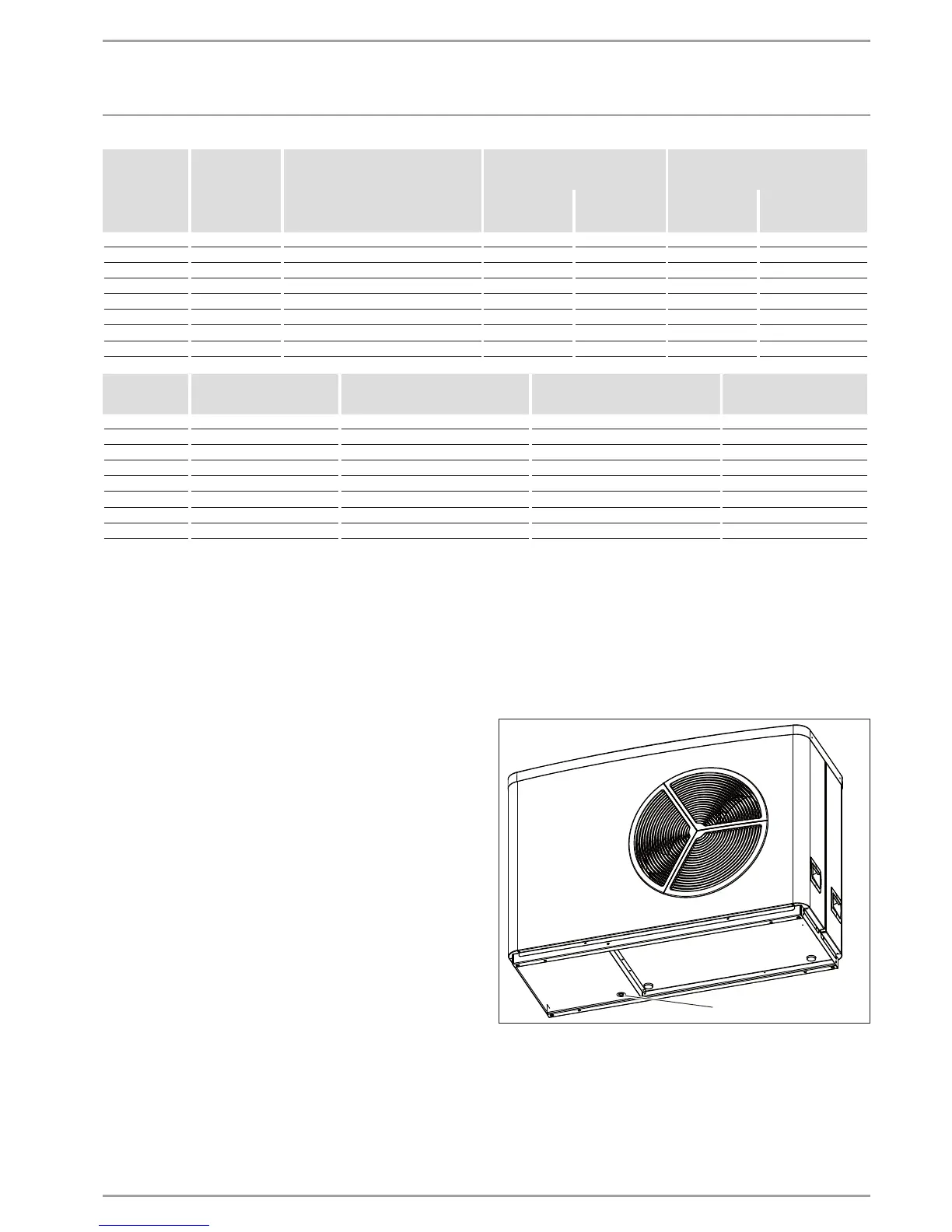
10.9 Condensate drain
A condensate drain connector is factory-fitted to the defrost pan
to enable any condensate to drain off.
26_03_01_1868
1
1 Condensate drain
Observe chapter "Electrical connection/ Ribbon heater".
If the appliance is sited on foundations, the condensate drips
freely into the condensate drain pipe.
If the appliance is mounted on a bracket or T-support, attach
a condensate hose to the condensate drain.
Protect the condensate hose against frost with sufficient
thermal insulation.

 Loading...


