www.stiebel-eltron.com 19
11.4 WPL25AS | WPL25ACS
Connect the cables according to the following diagram.
BUS
X2
L
H
T
„+“
X5 / DHC X3 / WP X4 / Steuerung
N LL N L N
L
ON
-
ERR
N
3,0 kW L N PE
3,2 kW L N PE
6,2 kW L N L N PE
1/N/PE~230/50
C 32A
1/N/PE~230/50
C 16A
1/N/PE~230/50
C 20A
D0000037825
1
1 Earth terminal for screening the LV lead
X2
BUS High H
BUS Low L
BUS earth
BUS "+" (is not connected)
X3
L, N, PE
X4
-
ON
ERR
Power supply: L, N, PE
X5
L, N, L, N, PE
3.0kW L N PE
3.2kW L N PE
6.2kW L N L N PE
Earth the LV lead by inverting the screen over the external
sheath and clamping it under the earth terminal.
Then check that the strain relief fittings are working as
intended.
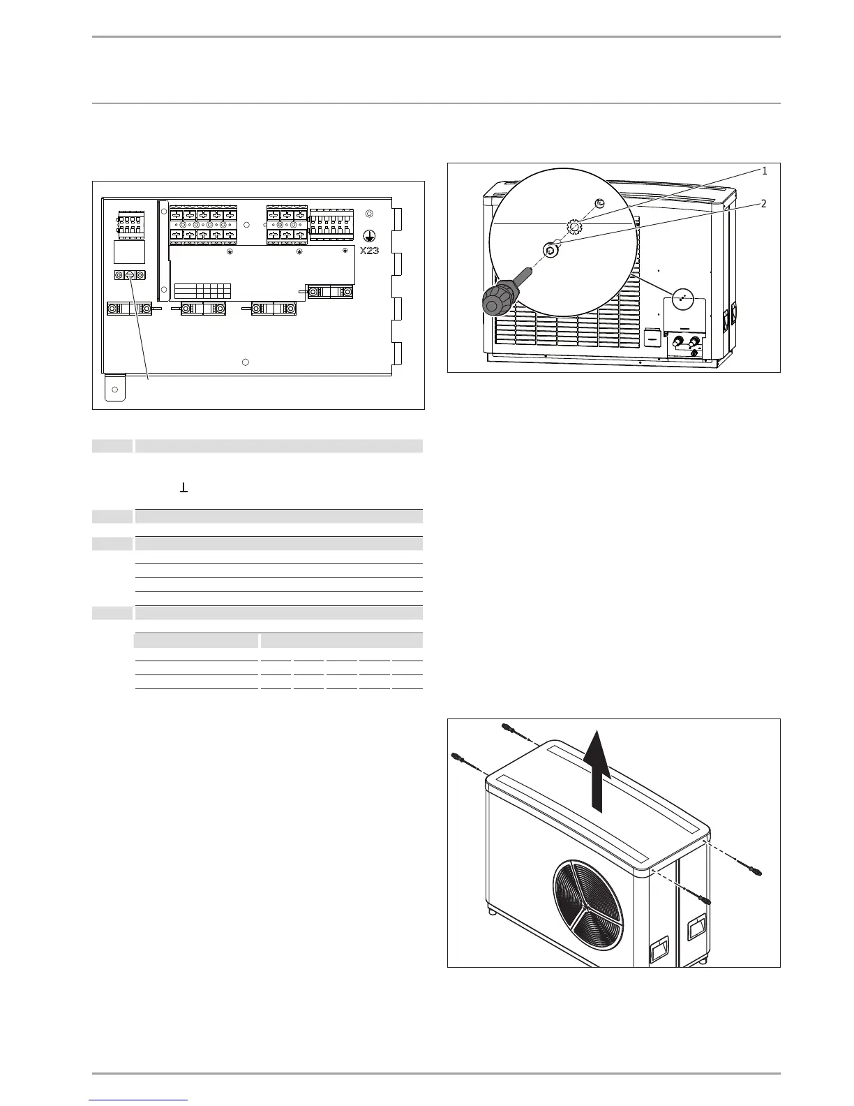
11.5 Closing the terminal area
D0000035356
1
2
1 Serrated washer
2 Screw
Secure the cover with the screw and serrated washer.
Connect the following components to the heat pump manag-
er in accordance with the technical guides:
- Circulation pump for the heat consumer side
- Outside temperature sensor
- Return sensor (only for operation with buffer cylinder)
11.6 Ribbon heater
A ribbon heater (see chapter "Installation/ Appliance description/
Accessories/ Further accessories") can be fitted to the condensate
pan and the condensate hose.
Install a ribbon heater when mounting on the wall bracket or
T-support.
When installing on foundations or the mounting bracket, we rec-
ommend installing a ribbon heater if the routing of the condensate
hose means it is at risk of frost or is fully exposed to the elements.
Access to the terminal area
26_03_01_1544
Remove the cover.

 Loading...


