www.stiebel-eltron.com 11
≥300
1
2
3
4
5
D0000058719
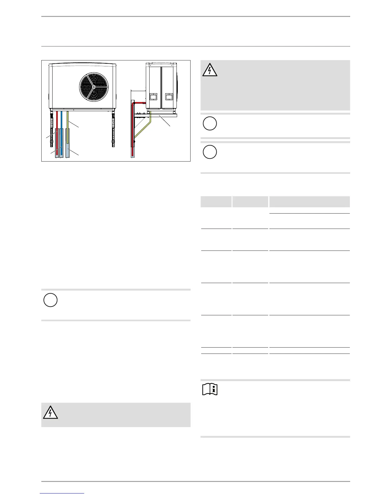
1 Heating flow
2 Heating return
3 Condensate drain
4 Condensate drain conduit
5 Wall mounting bracket
Observe the structural limits of the wall mounting bracket
used.
See the dimensioned connection drawing for the correct
spacing between holes (see chapter "Specification/ Dimen-
sions and connections").
9.6 WPM heat pump manager
A WPM heat pump manager is required to operate the appliance.
This controls the entire heating system.
Observe the WPM installation instructions during installation.
9.7 Buffer cylinder
!
Material losses
A buffer cylinder with diffusion-proof insulation is es-
sential to enable cooling by means of fan convectors. The
emergency/booster heater must be connected.
We recommend the use of a buffer cylinder to ensure trouble-free
appliance operation.
The buffer cylinder provides hydraulic separation of the volume
flows in the heat pump circuit and heating circuit, and also serves
as an energy source for defrosting.
For operation without a buffer cylinder, observe the details
in chapter "Minimum flow rate with individual room control
via remote control in systems without buffer cylinder".
9.8 Preparing the electrical installation
WARNING Electrocution
Carry out all electrical connection and installation work
in accordance with national and regional regulations.
WARNING Electrocution
The connection to the power supply must be in the form
of a permanent connection. Ensure the appliance can be
separated from the power supply by an isolator that dis-
connects all poles with at least 3mm contact separation.
This requirement can be met by contactors, isolators,
fuses, etc.
!
Material losses
The specified voltage must match the mains voltage. Ob-
serve the type plate.
!
Material losses
Provide separate fuses/MCBs for the three power circuits,
i.e. those of the appliance, the control unit and the elec-
tricemergency/booster heater.
Use cables with the relevant cross-sections. Observe the ap-
plicable national and regional regulations.
1x C 20 A
Compressor
(1-phase)
WPL 15 AS
WPL 15 ACS
2.5mm² when routing above the surface
4.0mm² when routing in a wall
1x C 35A
Compressor
(1-phase)
WPL 25AS
WPL 25ACS
6.0mm² when routing in a wall
3x C 16 A
Compressor
(3-phase)
WPL20A
WPL20AC
WPL25A
WPL25AC
2.5mm²
2x B 16 A
Electric emergen-
cy/booster heater
WPL15AS
WPL15ACS
WPL25AS
WPL25ACS
2.5mm²
3x B 16 A
Electric emergen-
cy/booster heater
WPL20A
WPL20AC
WPL25A
WPL25AC
2.5mm²
1x B 16 A Control unit 1.5mm²
The electrical data can be found in the chapter "Specification".
You require a screened J-Y (St) 2x2x0.8mm² cable as a bus cable.
Note
The appliance includes an inverter for the variable speed
compressor. In the event of a fault, inverters can cause
DC residual currents. If RCDs are provided, they must be
type B AC/DC-sensitive.
A DC residual current can block type A RCDs.
Ensure that the appliance power supply is discon-
nected from the distribution board.

 Loading...


