FS 510 C-M, FS 560 C-M
English
18
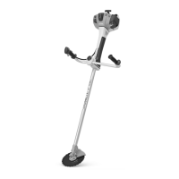
Recommendation: Use grass cutting
blades with a grass shield on the
gearbox, see chapters on "Mounting the
Deflector" / "Mounting the Grass Shield".
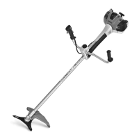
Deflector (3) is approved for shredder
blades only and must therefore be
mounted before fitting a shredder blade,
see chapter on "Mounting the Deflector".
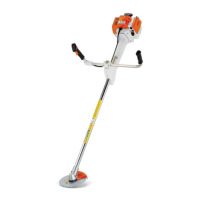
Stop (4) is approved for circular saw
blades only and must therefore be
mounted before fitting a circular saw
blade.
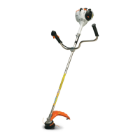
Mounting the Deflector
Deflectors (1, 2 and 4) are mounted to
the gearbox in the same way.
N Remove dirt from joints on gearbox
and deflector – make sure that no
dirt gets into the screw holes in the
gearbox – see section on "Plugs".
N Place the deflector on the gearbox
(5).
N Insert the screws (6) and tighten
them down firmly.
Mounting shredder deflector
Owing to the high loads on the shredder
deflector (3) and country-specific
regulations on the use of the machine for
shredding, the deflector must be
properly mounted to the machine.
A special screwdriver bit is required to
mount this deflector. The bit is available
only from specialist retailers. It has a
special drive for rotating the screws and
only allows the screws to be tightened.
Once tightened, the screws can no
longer be loosened – not even with the
special tool.
STIHL therefore recommends: Have the
shredder deflector mounted by your
STIHL dealer.
A "shredder deflector mounting kit" is
available as a special accessory for
retrofitting machines with a shredder
deflector. Depending on the machine's
original equipment, a "shredder blade
retrofit kit" may also be needed for the
conversion. Neither of these kits include
the shredder blade – it must be ordered
separately.
The "shredder blade retrofit kit" contains
clamps which butt against the gearbox
and have to be secured to the drive tube.
The kit also contains the shredder
deflector which is mounted to the
clamps.
– Installing the clamps
– Lower clamp (1): Identified by two
lugs (2) on its longitudinal axis, eight
tapped holes and a lateral notch (3).
– Upper clamp (4): Identified by holes
marked 1 to 4 and a lateral lug (5).
 Loading...