40 Series 4144 Components FC, FS, KM
– Check operation.
The throttle trigger must be locked
in position when the interlock lever
is not depressed.
: Release the throttle trigger – it
must return to the stop
– Reassemble all other parts in the
reverse sequence.
– Tightening torques, b 3.4
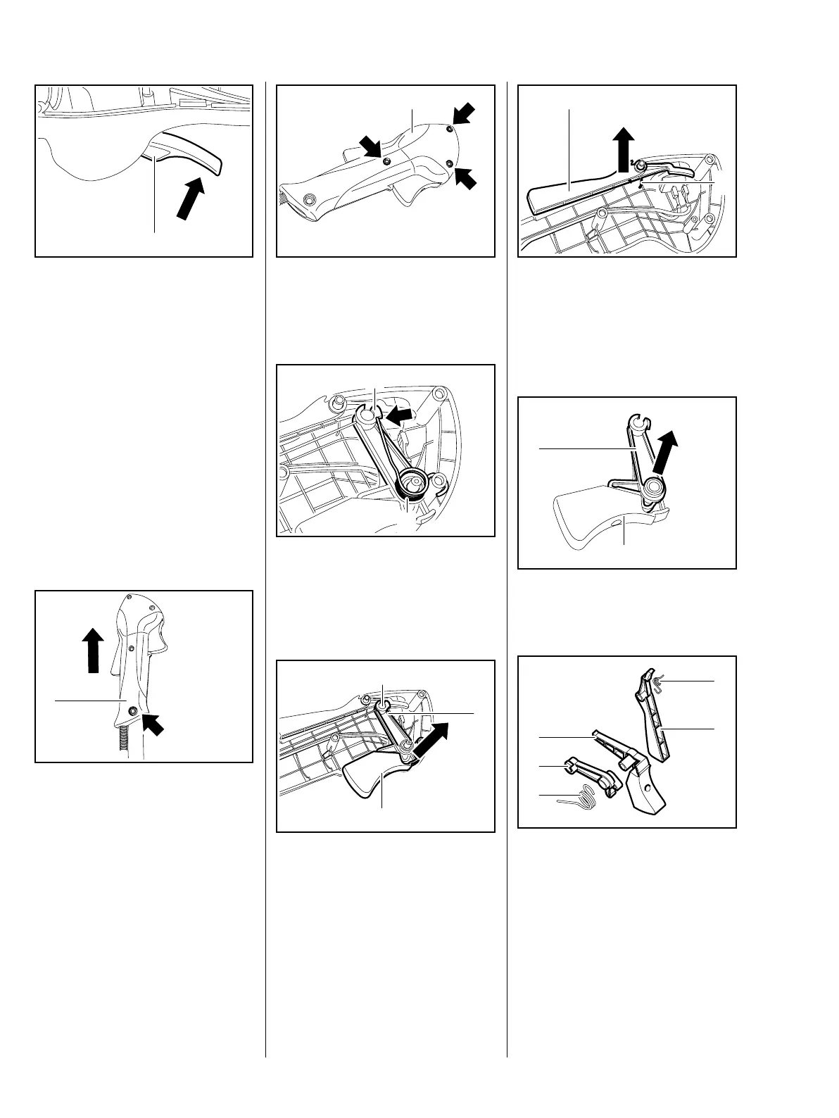
7.4 Throttle Trigger/Interlock
Lever (Bike Handle)
: Take out the screw (arrow).
– Pull off the control handle (1).
545RA145 TG
1
1
545RA073 TG
: Take out the screws (arrows).
– Remove the handle molding (1).
: Disconnect the leg (arrow) from
the lever (1).
– Remove the torsion spring (2).
: Remove the throttle trigger (1)
and lever (2).
– Disconnect the throttle cable (3).
545RA146 TG
1
545RA147 TG
1
2
545RA148 TG
1
3
2
: Carefully remove the interlock
lever (1) – tension of torsion
spring (2) is suddenly relieved.
– Remove the torsion spring (2).
: Pull the lever (1) off the throttle
trigger (2).
– Check the interlock lever (1),
throttle trigger (2), lever (3) and
torsion springs (4+5) and replace
if necessary,
545RA150 TG
1
2
545RA149 TG
1
2
545RA151 TG
4
1
2
3
5
 Loading...