61Series 4144 Components FC, FS, KM
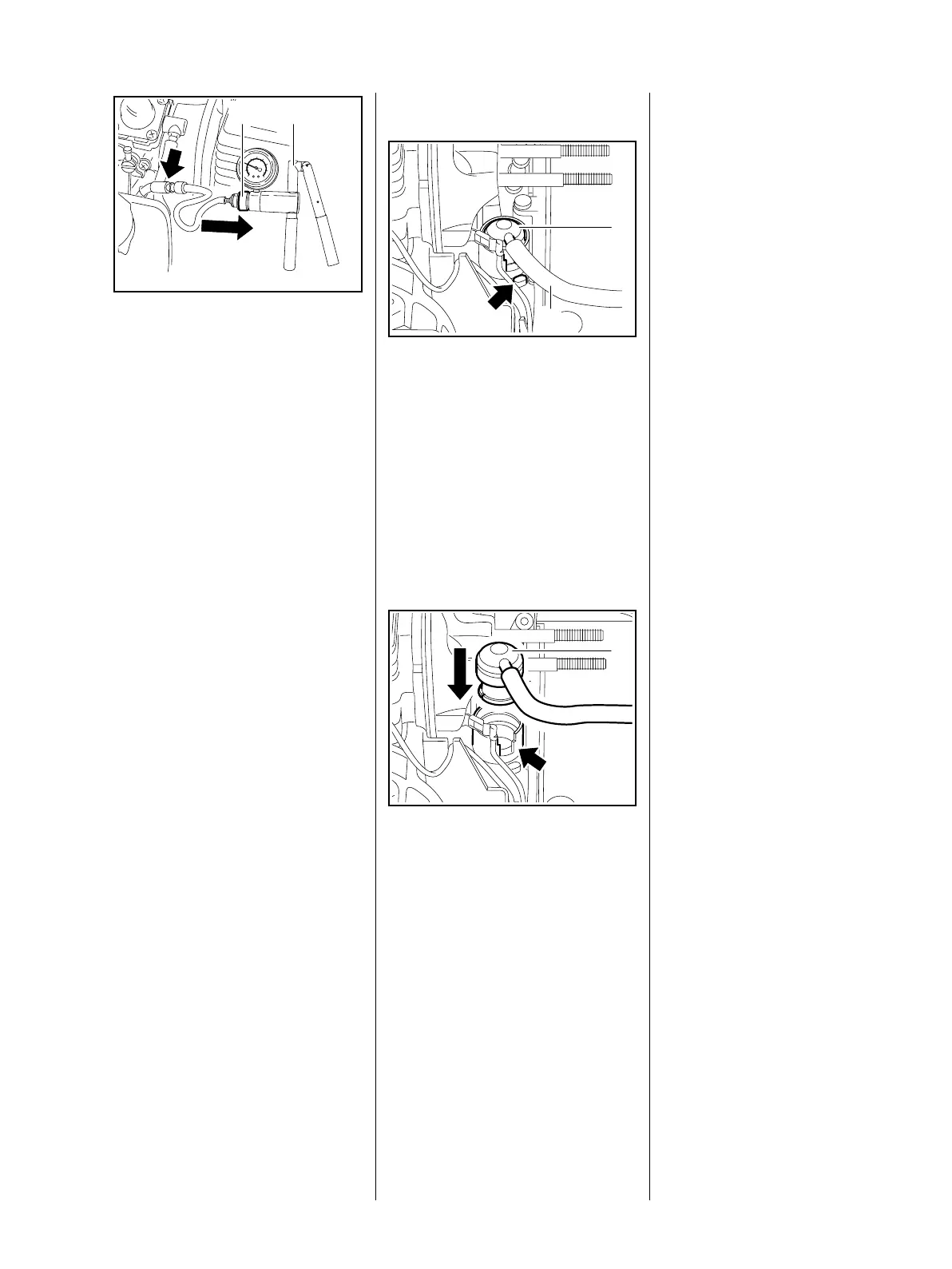
Pressure test
: Push the ring (1) to the right and
connect the pump (2)
0000 850 1300 to the nipple
(arrow)
– pressurize the fuel tank.
– Operate the pump until the
pressure gauge indicates a
pressure of 0.5 bar. If this
pressure remains constant for at
least 20 seconds, the tank,
including the tank vent, is airtight.
If the pressure drops, the leak
must be located and the faulty
part replaced.
– Reassemble in the reverse
sequence.
545RA216 TG
1 2
8.8.2 Removing and Installing
– Remove the carburetor, b 8.2
: Pry the tank vent (1) out of its
seat using the rib (arrow) for
leverage.
– Pull the tank vent (1) off the hose
(1), check and replace if
necessary.
Always install a new tank vent.
– Connect the new tank vent to the
hose.
– Line up the tank vent so that its
stub fits in the recess (arrow).
: Push the tank vent with hose into
its seat until it snaps into place.
Make sure the hose is pushed fully
on to the filter housing stub.
– Reassemble all other parts in the
reverse sequence.
1
545RA217 TG
2
1
545RA218 TG
8.9 Fuel Intake
8.9.1 Pickup Body
Any impurities mixed with the fuel
are retained by the pickup body
(filter). The fine pores of the filter
eventually become clogged with
minute particles of dirt. This restricts
the passage of fuel and results in
fuel starvation.
In the event of problems with the
fuel supply system, always check
the fuel tank and the pickup body
first.
– Troubleshooting, b 4.4 or
b 4.5
Clean the fuel tank if necessary:
– Open the tank cap and drain the
tank.
– Pour a small amount of clean
gasoline into the tank. Close the
tank and shake the saw
vigorously.
– Open the tank again and drain it.
– Dispose of fuel properly in
accordance with environmental
requirements, b 1

 Loading...