48 MS 650, MS 660
Exercise extreme caution when
troubleshooting or carrying out
maintenance and repair work on the
ignition system. The high voltages
that occur can cause serious or
even fatal accidents.
Troubleshooting on the ignition
system should always begin at the
spark plug – b 4.5
The electronic (breakerless) ignition
system basically consists of an
ignition module (1) and flywheel (2).
1
2
178RA055
VA
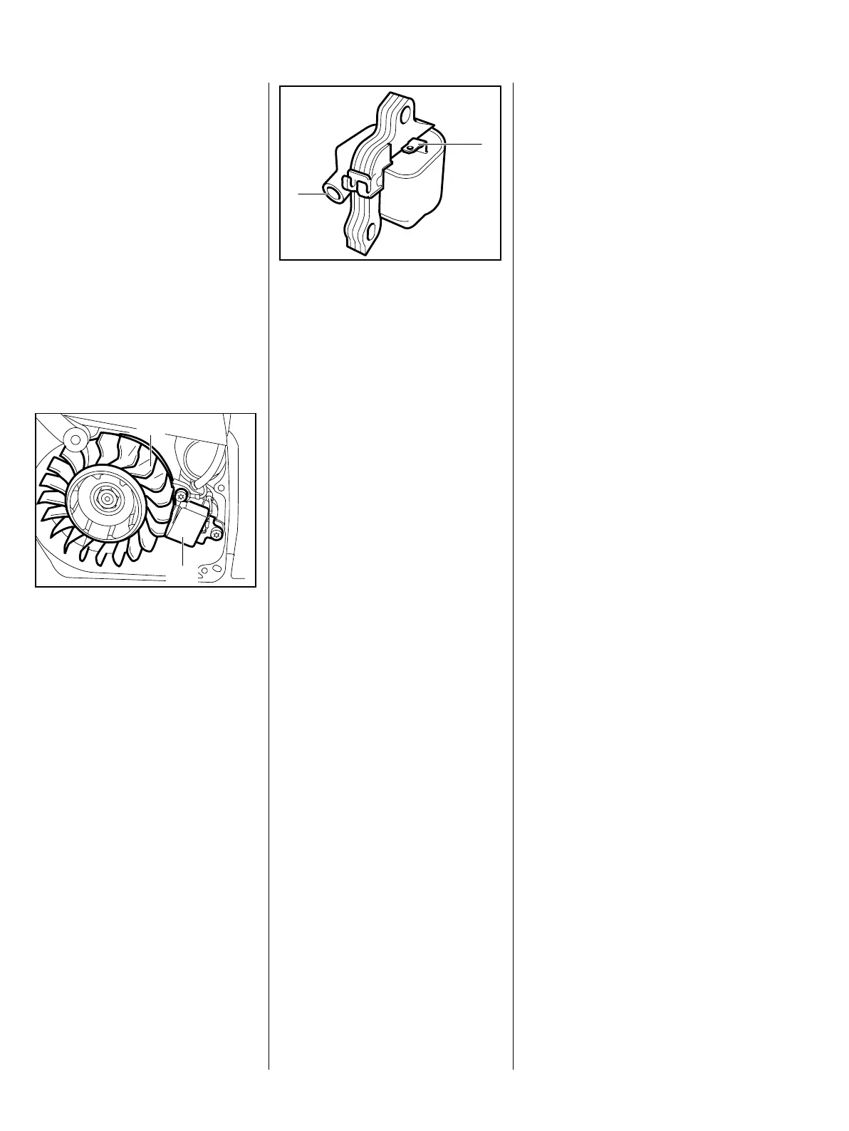
The ignition module accommodates
all the components required to
control ignition timing. There are
two electrical connections on the
coil body:
: High voltage output (1) for
ignition lead
VA
176RA149
1
2
: Connector tag (2) for short
circuit wire
Testing in the workshop is limited to
a spark test.
A new ignition module must be
installed if no ignition spark is
obtained (after checking that wiring
and stop switch are in good
condition)
Ignition timing is fixed and cannot
be adjusted during repair or
servicing work
Since there is no mechanical wear
in these systems, ignition timing
cannot get out of adjustment as a
result of wear.
7. Ignition System 7.1 Ignition Module 7.2 Ignition Timing