67MS 650, MS 660
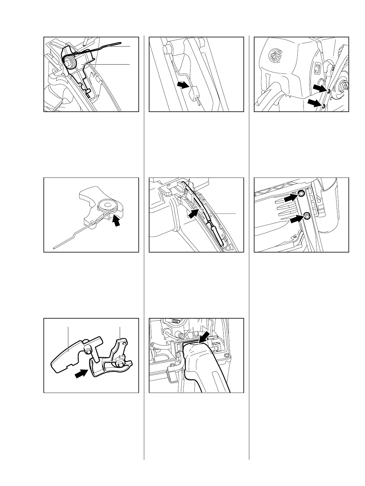
: Remove the throttle trigger (1)
with torsion spring (2).
178RA104
2
VA
1
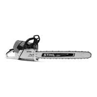
: Remove the torsion spring from
the throttle trigger.
Installing
VA
212RA129
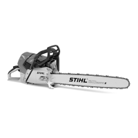
: Fit the interlock lever (1) so that it
engages the throttle trigger (2)
when operated (arrow).
VA
178RA231
1 2
: When installing, make sure the
torsion spring is under the
interlock lever and engages the
notch (arrow).
VA
138RA128
: On machines with handle heating
the wires (1) from the heating
element must be in the guide
(arrow) under the interlock lever.
VA
212RA130
: Position the handle molding so
that its front edge (arrow)
engages the frame (1).
Reassemble all other parts in the
reverse sequence.
178RA106
VA
1
: Take out the screws (arrows).
VA
178RA107
: Take out the screws (arrows).
– Remove the front handle.
Reassemble in the reverse
sequence.
178RA108
VA
Machines with handle heating
– Remove the front handle with
heating element – b 14.4
– Check the heating element –
b 14.1
10.3 Front Handle